6
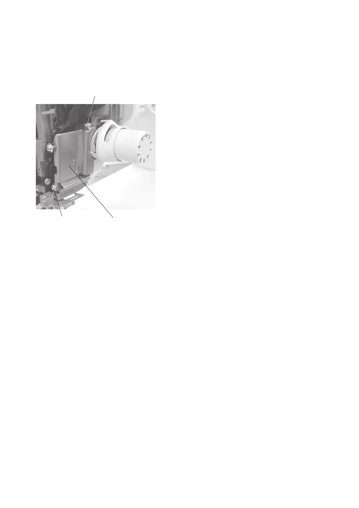
Changing external parts (6)
To remove:
Remove the face plate, top cover and thread guide cover.
2. Loosen the setscrews A and B, and remove the arm
thread guide (unit).
To attach:
3. Follow the steps of removal procedure in reverse.
Setscrew A
Setscrew B
Arm thread guide (unit)
Arm thread guide (unit)
INDEX
Changing external parts
Face plate
.................................................................................................1
Top cover
..................................................................................................1
Belt cover
.................................................................................................2
Base
............................................................................................................2
Power supply cover
.............................................................................3
Thread cutter cover
............................................................................3
Front cover
............................................................................................... 4
Thread guide coverr
............................................................................5
Arm thread guide (unit)
...................................................................... 6
Replacing Electronic Components
Changing the printed circuit board A
.......7
Changing the printed circuit board K
.......8
Switching power supply unit ........................................................................13
Driving motor ...............................................................................................14
Thread tension unit ......................................................................................15
Mechanical Adjustment
Feed dog height ...........................................................................................16
Needle drop position .................................................................................... 17
Clearance between needle and tip of the rotary hook (method 1) ............... 18
Clearance between needle and tip of the rotary hook (method 2) ............... 19
Hook timing .................................................................................................. 20
Needle bar height ........................................................................................21
Backlash between hook drive gear and lower shaft gear ............................22
Upper shaft shield plate position .................................................................23
Upper thread tension ...................................................................................24
Tension release mechanism ........................................................................25
Replacing needle threader hook .................................................................. 26
Needle threader hook position ..................................................................... 27
Thread drawing lever ...................................................................................28
Upper feed dog (1) ......................................................................................29
Upper feed dog (2) ......................................................................................30
Upper feed dog (3) ......................................................................................31
Buttonhole lever. .......................................................................................... 32
Thread cutter ...............................................................................................33
Presser bar lifter position .............................................................................34
Presser foot lifter stopper position (1) .......................................................... 35
Presser foot lifter stopper position (2) .......................................................... 36
Automatic presser foot lifter initializing position ...........................................37
Presser bar height .......................................................................................38
Stretch stitch feed balance ..........................................................................39
Needle plate switch .....................................................................................40
Knee lifter ....................................................................................................41
Remaining bobbin thread sensor ................................................................. 42
PARTS LIST
.......................................................................................... 43-73