19
MO200
5200QDC
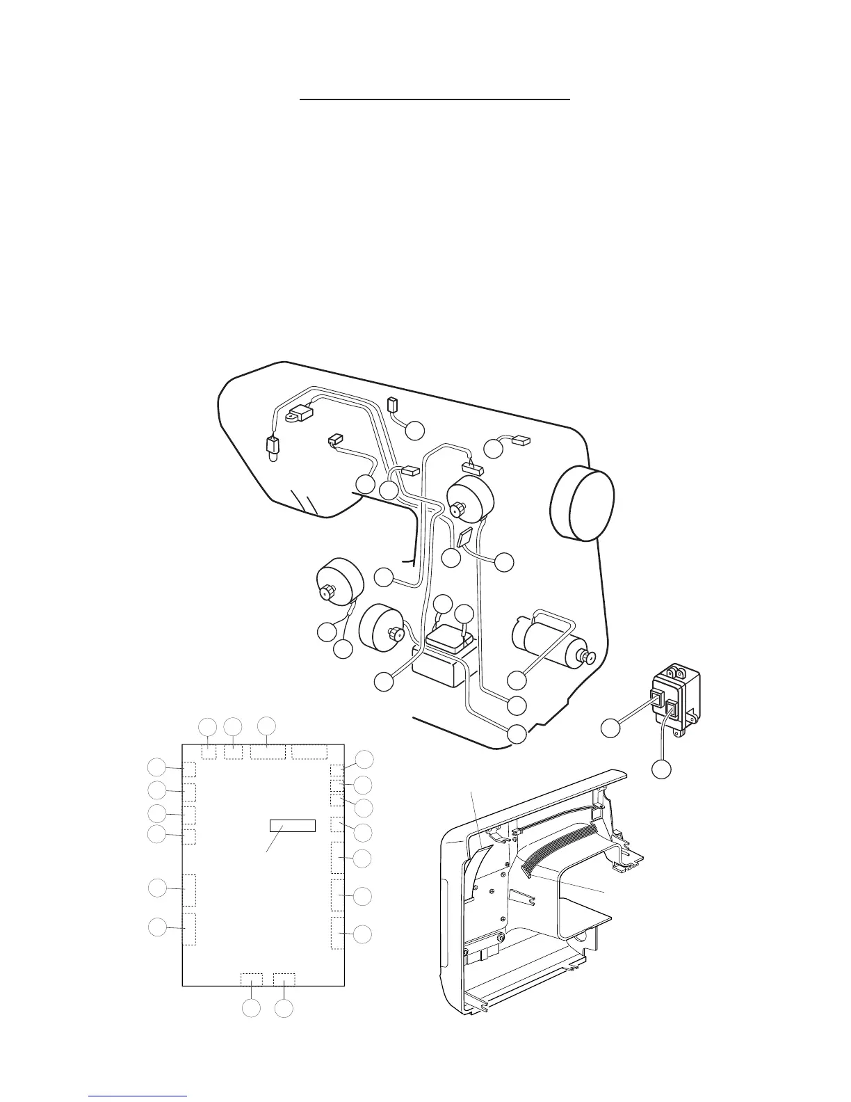
Flexible cable
CONNECTOR DIAGRAM
REFER TO THE DIAGRAM FOR LOCATING THE CONNECTOR POST ON THE CIRCUIT
BOARD
A : Buttonhole sensor (BLK)
B : Sewing light (WHT)
C : Upper shaft sensor (BLK)
D : Feed motor (BLK)
E : Zigzag width motor (WHT)
F : DC motor (WHT)
G: Power transformer (primary circuit) (BLK)
H : Power transformer (secondary circuit) (RED)
I : Printed circuit board “F” (BLK)
J : Bobbin winder switch (BLU)
K : Presser foot lifter switch (BLK)
L : Thread tension switch (BLU)
M: Arm lamp (RED)
N: Needle plate switch (RED)
O: Needle plate motor (WHT)
P: Machine plug (secondary circuit) (WHT)
Q: Printed circuit board “G2” (RED)
R: Receptacle (primary) (WHT)
A
B
C
D
E
F
G
H
J
K
L
M
N
O
Printed circuit board "F"
A
B
C
D
E
F
H
I
G
J
K
L
Q
M
N
O
P
Flexible cable
R
R
P
Q