24
MO200
5200QDC
F1:
AC125V 3.15A
F2:
AC125V 2.5A
F3:
AC125V 2.5A
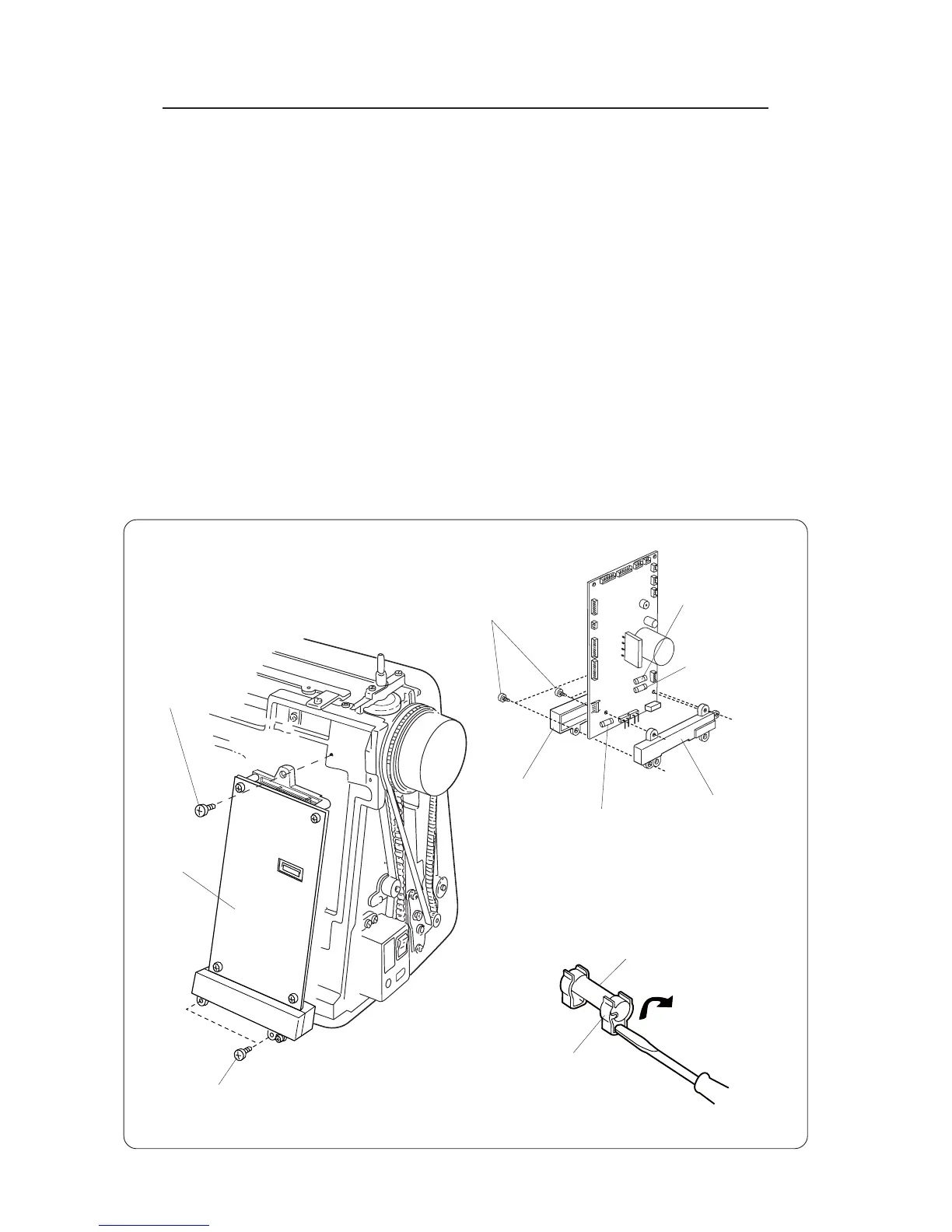
REPLACING PRINTED CIRCUIT BOARD A AND FUSES
REPLACING PRINTED CIRCUIT BOARD "A"
TO REMOVE:
1. Remove the front cover (see page 5).
2. Unplug the connectors from the printed circuit board "A".
3. Remove the 3 setscrews and remove printed circuit board "A".
TO INSTALL:
4. To install, follow the above procedure in reverse.
REPLACING THE FUSES
TO REMOVE:
5. Remove the printed circuit board "A".
6. Remove the 4 setscrews and remove the printed circuit board "A" case and case lid.
7. Remove the fuse (pry it out with a screwdriver).
TO INSTALL:
8. Follow the above procedure in reverse.
Setscrews (A)
Setscrews (A)
Setscrews (B)
Printed circuit
board "A"
Printed circuit
board "A" case
Fuse holder
Fuse
Printed circuit
board "A" case lid