15
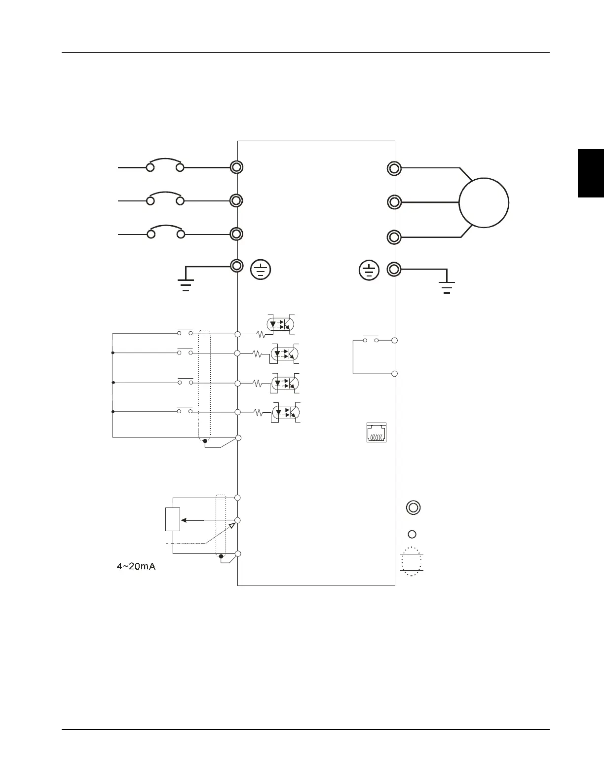
3.1 Basic Wiring Diagram
Users must connect wiring according to the circuit diagram shown below. Please follow all
National and State wiring codes, when wiring the FC100.
RS-485
6 1
RA
RC
120VAC/28VDC 3A
0 10VDC
VR 3K 5K
AVI
GND
+10V 10mA(MAX)
3
2
1
VR
RJ-11
1:+EV
2:GND
3:SG-
4:SG+
+18V
+18V
+18V
S1
GND
+18V
4.7K
S2
4.7K
4.7K
4.7K
Factory default settings
Forward/Stop
Reverse/Stop
Reset
Multi-step 1
Common Signal
Power supply for Potentiometer
Master Freq. setting
Analog voltage
Analog current
Motor
Multi-function indication
output contacts
Factory default:
Fault Indication
Main circuit (power)
terminals
Control circuit terminals
Shielded leads
*
NOTE: Do not plug in a Modem or telephone line to the RS-485 communication port,
permanent damage may result. Terminals 1 & 2 are the power source for the
optional copy keypad and should not be used while using RS-485
communication.
Main Circuit Power
Communication
port
+10V
3
FC100 Series User Manaul
Chapter 3 Wire diagram and terminal explanation
 Loading...