EasyManua.ls Logo

Janson Controls FC100 Series - User Manual

Janson Controls FC100 Series
108 pages
Print Icon
To Next Page IconTo Next Page
Loading...
1
.
Preface
Thank you for purchasing the FC100 series AC drive developed by our company.
FC100 series AC drive is a compact small power AC drive. It is an economic model
specialized for the small automation equipments, especially for electronic equipments,
food packaging, woodworking and other applications.
FC100SeriesACDriveFeatures
AdvancedV/FControl / Vector ControlAlgorithm:
Adjustable V/F Control is more stable at low speed, high torque output at low
frequency
and better dynamic performance.
.
MultipleFunctions:
Multi-stage speed control, simple PLC, PID and pulse counting control.
.
StableandReliableAnti-tripFunction:
Stable and reliable overvoltage/overcurrent stalling control algorithm, non-stop
control
function to prevent frequent trip in complex applications.
This manual describes the functions and features and correct use of FC100 series
AC drive, including product selection, parameter setting, running commissioning,
troubleshooting and routine maintenance and other related matters. Please read
this manual carefully to make sure the correct installa-tion and operation and
maintenance to achieve the high performance of this AC drive. Please hand this
manual to the users and keepers of this AC drive.
.
UnpackingInspectionCautions
Every AC drive have been tested strictly in factory prior to shipment. Upon
unpacking, check:
Whether the product is damaged;
Whether the nameplate model and AC drive ratings are consistent with your
order.
Whether the box contains the AC drive, certificate of conformity, user manual
and
warranty card. If you find any omission or damage, contact our company or your
supplier immediately.
FC100 Series
Preface

Table of Contents

Question and Answer IconNeed help?

Do you have a question about the Janson Controls FC100 Series and is the answer not in the manual?

Janson Controls FC100 Series Specifications

General IconGeneral
Enclosure RatingIP20
MountingDIN rail
Supply Voltage24 VAC
CommunicationBACnet MS/TP, Modbus RTU
Input Voltage24 VAC/VDC
Output TypeTriac
Operating Temperature-20°C to 60°C

Summary

Preface

Chapter 1 Product Information

1.1 Naming Rules

Defines the model code structure for product identification.

1.2 Name Plates

Explains the information presented on the AC drive's nameplate.

1.3 FC100 Series AC Drive

Lists available FC100 AC drive models and their specifications.

1.4 Size and Dimensions

Provides physical dimensions and mounting clearances for the unit.

1.5 Specifications

Details electrical, control, environmental, and operating specifications.

Chapter 2 Storage and Installation

2.1 Storage

Outlines recommended ambient conditions for storing the AC drive.

2.2 Installation

Covers installation precautions, mounting guidelines, and air flow requirements.

Chapter 3 Wiring Diagram and Terminal Explanation

3.1 Basic Wiring Diagram

Illustrates the fundamental wiring connections for power and control circuits.

3.2 Terminal Explanations

Explains the function of each terminal symbol on the AC drive.

3.3 Control Terminals Explanations

Details terminal symbols, functions, and factory settings for control inputs.

3.4 Main Circuit Wiring

Shows the main circuit wiring for AC line input and motor output.

3.5 Wiring Notes

Provides essential precautions and notes for safe and correct wiring.

Chapter 4 Keypad Operation

4.1 Description of Digital Keypad

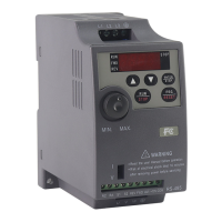
Describes the components and functions of the digital keypad interface.

4.2 Detailed way for how to use keypad

Explains the step-by-step procedures for using the keypad for operations.

Chapter 5 Function Parameters Table

Chapter 6 DESCRIPTION OF PARAMETER SETTINGS

Group P0: User Parameters

Details parameters for main display data selection and alarm records.

Group P1: Basic Parameters

Covers essential parameters like frequency setting and start signal selection.

Group P2: Parameters of basic applications

Outlines parameters for start/stop modes and basic application settings.

Group P3: Input and Output Function Parameters

Details parameters for analog input/output and multifunction terminals.

Group P4: Secondary Application Group

Covers parameters for jog, counter, and torque limiting functions.

Group P5: PLC Control(Special Operation)

Explains parameters for PLC memory, start mode, and running modes.

Group P6: PLC Control(Special Operation)

Details parameters for PID control starting, operation modes, and set points.

Group P7: RS-485 Communication

Covers RS-485 communication speed, mode, and address settings.

Group P8: Advanced application parameters

Describes parameters for parameter lock, system frequency, and protections.

Chapter 7 Maintence and Inspection

6.1 Periodic Inspection

Lists basic check-up items to detect operational abnormalities.

6.2 Periodic Maintenance

Provides guidelines for periodic maintenance tasks and safety precautions.

Chapter 8 Troubleshooting and Fault Information

Common Problems and Solutions

Lists common faults, their possible reasons, and corrective actions.

Related product manuals