70
10: Timer 1 reached 11: Timer 2 reached
When inverter arrives at setting value, this contact is ON, when timer start-up
signal is removed, this contact is reset.
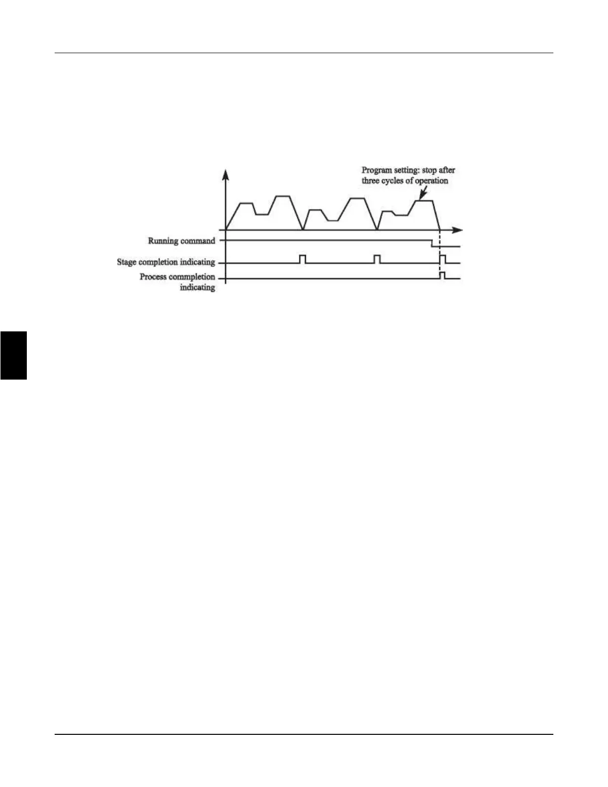
12: Stage completion indication
In the PLC operation mode, inverter output this pulse signal when inverter
finished a section of program.
13. Process completion indication
In the PLC operation mode, inverter output this pulse signal when inverter
finished the entire program.
14. PID upper limit
When PID feedback quantity exceeds setting value of upper limit, this contact is
ON.
15: PID lower limit
When PID feedback quantity is lower than setting value, this contact is ON.
16: 4-20mA cable open
When FIC input signal is disconnected, this contact is ON and alarms.
17: Overload detection
When inverter detects that motor overloads, this contact is ON.
18: Over torque detection
When inverter detects over torque, this contact is ON.
26: Winding function completeWhen winding function is complete, this contact
is ON. When inverter stops, this contact is reset.
27: Set counter reached
When inverter implements external counter, and when count value arrives at
setting value (P425), this contact is ON.
28: Middle counter reached
When inverter counts, if count value arrives at setting value (P426), this contact
is ON.
29: constant pressure water supply (P325 is set to 29, RA and RC close (1)
indicate that the function of constant pressure water supply is effective. RA, RC
disconnection (0) indicates that the function of constant pressure water supply
is invalid.)
6
Chapter 6 Description of parameter setting
FC100 Series User Manaul