40
P014--P018. you can examine the frequency setting,actual output frequency, and
actual output current, output voltage,DC bus voltage of main circuit, According to
the above data,you can analyze the cause of fault and finds a solution quickly
which will help maintenance personnel in repair work
For FC100 Series, you can use parameter “F.00" to set the mian display data
It’s also possible to monitor the data directly through the parameters “P001~P018"
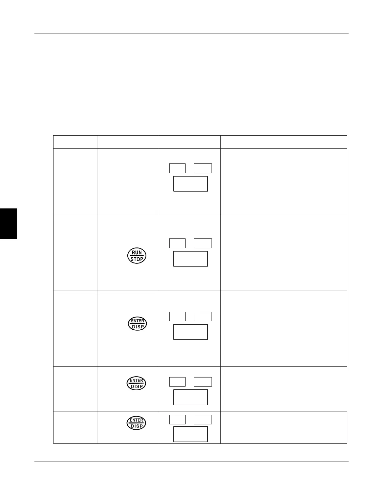
You may monitor the data by pressing switching key as shown in the below table
Procedure Press Key
Display
Explanation
1
2
3
4
5
Turn On Power
Press
Press
Once
Press
Once
Press
Once
Stop FWD
F50.0
1,Inverter is in standby mode.
2,The keypad displays frequency
setting.
FREE light is on, which means
that the keypad is displaying
frequency setting
RUN FWD
F50.0
Start inverter
1,Inverter is in running and RUN
light is on.
2,The image displays frequency
setting.
Forward light is on; inverter is in
Forward state.
RUN FWD
H50.0
Switch display; stop switching
when actual output frequency is
displayed.
Inverter is in Forward running
state.
① The actual output frequency is
50.0Hz.
Switch display; stop switching
when actual output current is
displayed.
① The actual current output is 0A
Stop FWD
A00.0
Stop FWD
Frd
Display running state
6
Chapter 6 Description of parameter setting
FC100 Series User Manaul
 Loading...