93
5-53
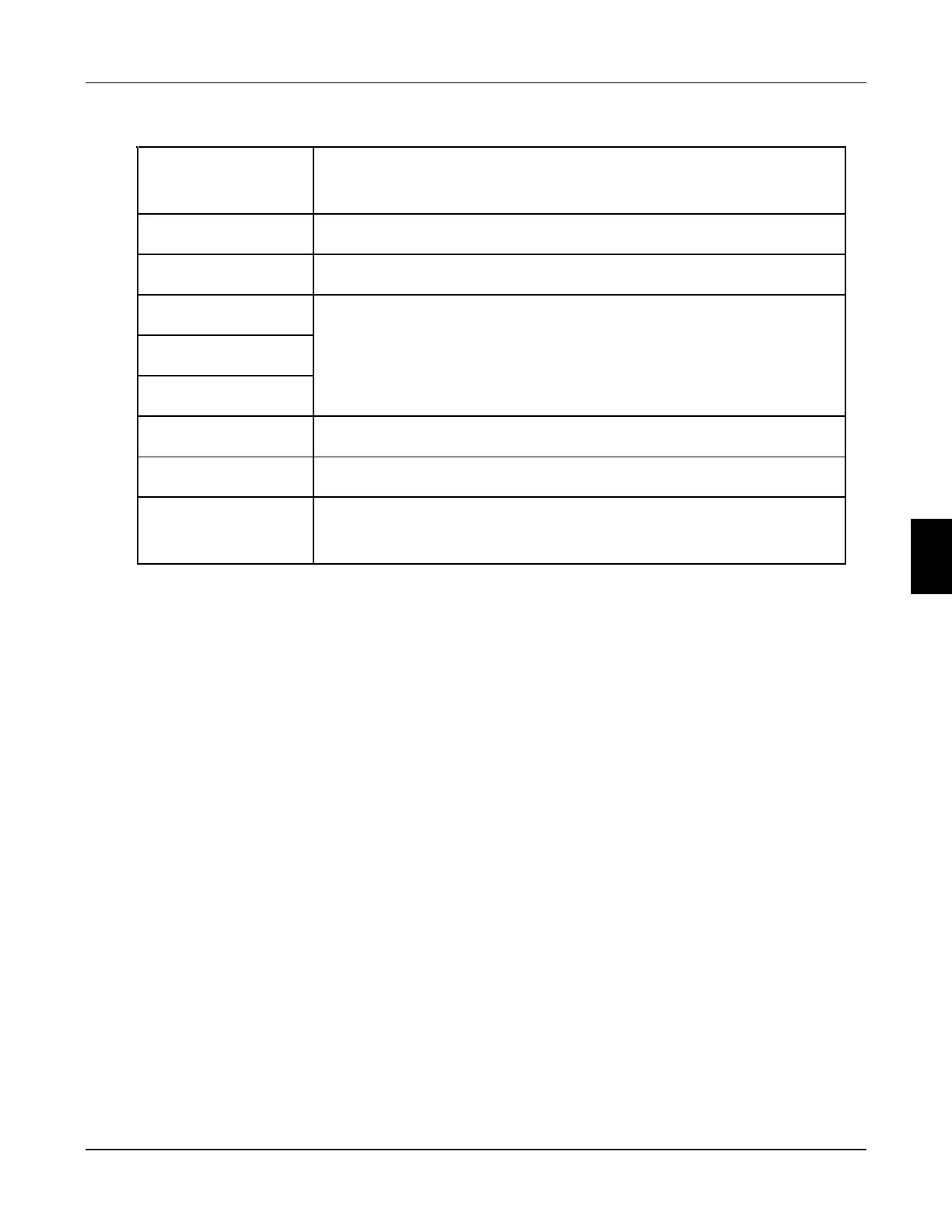
RTU mode:
START
Keep that zero - input signal is more than or equal to 10 ms
Address
Communication address: 8
-
bit binary address
Function
Function code: 8
-
bit binary address
DATA(n -1)
Data characters: n x 8
-bit data, n
= 16
DATA0
CRC CHK Low
CRC Check:
CRC CHK High
16-bit CRC Check consists of 2 8 -bit binary systems
END
Keep that zero-input signal is more than or equal to 10 ms
Communication Address
00H: All driver Broadcasts
01H: For inverter with 01st address
OFH: For inverter with 15th address
10H: For inverter with 16th address, by analogy, the maximum could reach 240.
Function code and Data Characters
03H: Read out the content of temporary storage
06H: Write a WORD into temporary storage; Function code 03H:
Read out the content of temporary storage.
For example: Driver address 01H, reads out the data characters in 2 successive
temporary storages as follows: Initial temporary storage address 2102H
Function code 06H: Write a WORD into temporary storage.
6
Chapter 6 Description of parameter setting
FC100 Series User Manaul
 Loading...