42 - 6
Drive Head Limited Slip Differential -
Assembly (cont’d)
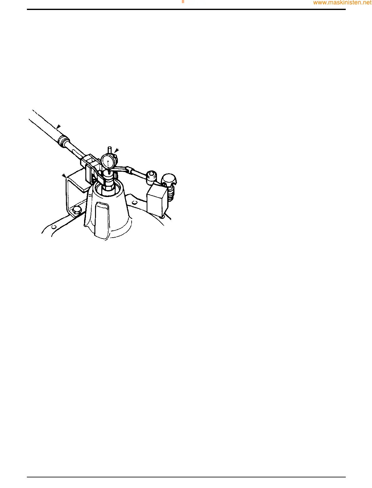
14 Fit dial test indicator (DTI) F. Ensure that the DTI is
mounted on the drive head and not on bracket D.
15 Set torque wrench G to 35 Nm (25.8 lbf ft) and measure
the end float while rotating the shaft.
16 To select the right size spacer 24, subtract the end float
obtained at step 7 from the solid spacer size (14.20
mm). Also subtract 0.04 mm to allow for theoretical
bearing tolerance and pre load. The result is the size of
spacer to be fitted from the solid spacer setting kit. If
there is no spacer of this size, fit the next nearest size
spacer, refer to Service Tools - Axles.
Example
Temporary spacer size 14.20
Subtract end-float 0.25
Total 13.95
Subtract tolerance & preload 0.04
Result 13.91
(No spacer available this size, use next nearest size
spacer i.e 13.900)
17 Remove sleeve B and temporary spacer, fit correct size
spacer from solid spacer setting kit, refer to Service
Tools - Axles. During removal take care to avoid
damaging the outer bearing.
18 Fit sleeve B. Tighten adapter C to no more than 50 Nm
to protect against bearing damage while spacer
selection is verified making sure the pinion is free to
rotate. Check there is no end float and pinion is free to
turn smoothly by hand. Remove adapter C and fit nut
16. Then check that rolling torque is less than 2.0 Nm. If
the rolling torque exceeds 2.0 Nm, check that the shaft
has been assembled correctly.
If the pinion is not free to rotate check the correct size
spacer has been fitted.
19 If rolling torque measured at step 10 is too high, fit the
next larger size spacer. If rolling torque is too low, fit
the next smallest size spacer. If a correct spacer is not
available from the range, check that drive head is
assembled correctly.
20 Remove adapter C and sleeve B. Fit new oil seal 25,
grease between seal lips before fitting. Fit coupling
yoke 22 and NEW stake nut 20.
21 Progressively torque tighten stake nut 20, occasionally
rotating coupling yoke, up to 250 Nm. Providing the
correct size spacer has been selected the rolling torque
should be between 2.3 and 3.4 Nm including seal drag.
Note: The nut tightening torque can be increased to a
maximum of 300 Nm provided that the pinion rolling torque
does not exceed the maximum of 3.4 Nm.
22 Finally stake the nut 20 into the slot.
23 Fit bearing caps 2A using bolts 2B tightened to 165 Nm
(121 lbf ft). Make sure the manufacturer's marks are
correctly aligned.
Note: Drivehead casing 2 and bearing caps 2A are
matched and should be renewed as a complete assembly
if damaged or worn.
24 Locate differential assembly (without bearings) into
drivehead.
Section F Transmission
9803/7130
Section F
42 - 6
Issue 1
Front Axle
FF
GG
348040
DD