10 Remove the adaptor block assembly retaining
setscrews 10 (4 off) and remove the block 11. Remove
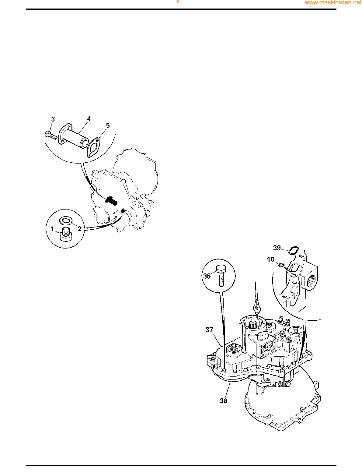
and discard the gasket 12.
11 Remove the casing retaining bolts 36.
12 Screw a lifting eye into a layshaft end cover bolt hole.
Using a suitable hoist, lift the rear casing 37 away from
the front casing 38. Pry bars may be used at the points
provided to assist in 'cracking' the joint. Remove and
discard the face 'O' rings 39 and 40.
61 - 2
Dismantling
1 Drain the oil from the casing into a suitable container by
removing the drain plug 1 and sealing washer 2.
Discard the sealing washer.
2 Remove suction strainer retaining bolts 3 and remove
the strainer 4. Remove and discard the strainer cap
gasket 5.
3 Remove and discard the oil filter.
4 Position the gearbox with the rear casing 37
uppermost.
5 Unscrew capscrews 6 and remove spacers 7 (4 off).
Remove the solenoid valve assembly 8. Retain the
spacers (4 off) but discard the 'O' rings 9 (4 off).
6 Remove output yoke 15 and brake disc 15A attachment
bolts 13 using service tool 892/00812. Remove yoke
15 and brake disc 15A from the output shaft 16.
7 Remove and discard the output shaft oil seals 17.
8 Remove the gear change turret retaining bolts 18 (4 off).
Remove the turret 19 and gasket 20. Discard the
gasket.
9 Remove layshaft cover plate retaining bolts 22 (6 off),
remove cover plate 24, discard gasket 25.
Section F Transmission
9803/7130
Section F
61 - 2
Issue 1
Syncro Shuttle Gearbox
S203970
S203991