Dismantling (Cont'd)
13 Remove the output shaft assembly 41.
14 Remove locking screws 42 (2 off) from selector forks 44
and 45.
15 Remove the detent plugs 46, springs 47 and balls 48 (2
off each).
16 Slide selector shafts 49 from selector forks 44 and 45.
17 Remove taper plug 50 from the casing. Thread a piece
of thin looped wire to the bottom of the RH selector
shaft locating hole. Using a small diameter screwdriver
through the taper plug hole, push the baulk roller 51
into the wire loop. Carefully withdraw the baulk roller.
18 Remove the layshaft assembly 52.
19 Remove the main shaft assembly 53.
20 Remove the reverser unit 54. See page 62-1 for
Dismantling and Assembly instructions.
21 Remove idler gear spacer 55, thrust washers 56, thrust
bearing 57, idler gear 58, needle roller bearings 59,
bearing spacer 59A, thrust washers 56 and thrust
bearing 57 from idler shaft 60.
22 Remove the idler shaft 60 using a slide hammer if
necessary.
23 Remove the bearing cups located in the front casing
using a slide hammer.
24 Turn the gearbox into the horizontal position.
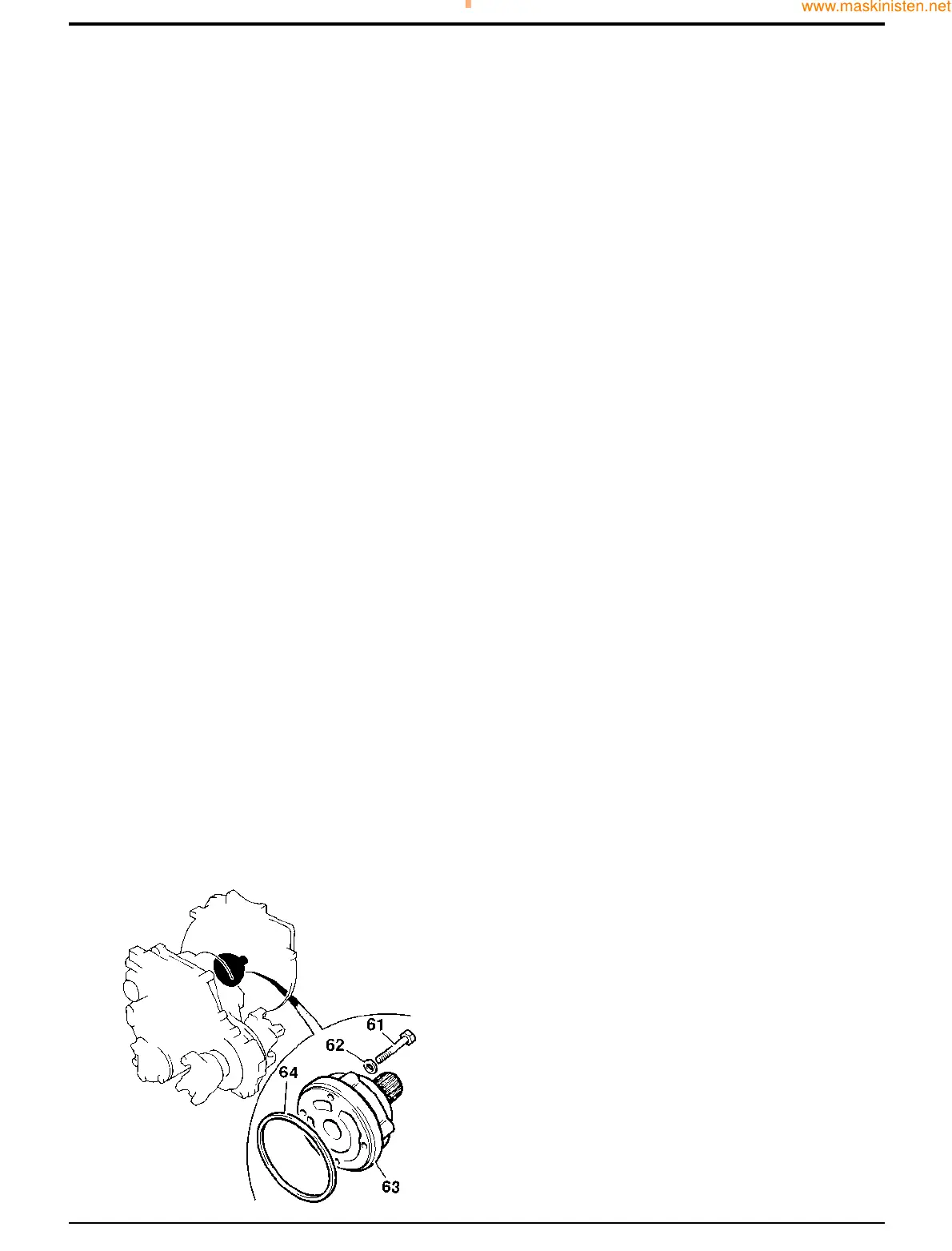
25 Remove the pump assembly retaining bolts 61 (4 off)
and washers 62 (4 off) and withdraw the pump
assembly 63. Remove and discard 'O' ring 64.
26 Remove the pump and shaft from the pump case.
27 Remove the bearing cups located in the rear casing
using a slide hammer.
61 - 4
Assembly
Note: All bearings must be lightly oiled before assembly.
Make sure all components are thoroughly clean and renew
all 'O' rings.
1 Clean the mating faces of front casing 38 and rear
casing 37.
2 Fit new bearing cups into front and rear casings using a
bearing dolly.
3 Fit the idler shaft 60 using a soft faced hammer.
4 Fit the idler gear assembly (thrust washers 56, thrust
bearing 57, needle roller bearings 59, bearing spacer
59A, idler gear 58, thrust washers 56, thrust bearing 57
and idler gear spacer 55).
5 Fit the reverser unit 54.
6 Fit the main shaft assembly 53.
7 Fit the layshaft assembly 52.
8 Fit the output shaft assembly 41.
9 Thread the RH gear selector rod 49 through selector
fork 45 and into the casing. Secure with locking screw
42. Torque tighten to 35 Nm (25.8 lbf ft).
10 Using a piece of looped wire, lower the baulk roller 51
down the LH selector rod channel in the casing. When
in position at the bottom, push the roller into position
using a small screwdriver through the taper plug hole
(item 50). Remove the wire and screwdriver. Fit the
taper plug 50 and torque tighten to 28 Nm (20.7 lbf ft).
11 Thread the LH selector rod 49 through selector fork 44
and into the casing. Secure with locking screw 42.
Torque tighten to 35 Nm (25.8 lbf ft).
12 Fit detent balls 48, springs 47 and plugs 46 (2 off each).
Torque tighten plugs to 35 Nm (25.8 lbf ft).
13 Screw a lifting eye into a layshaft housing bolt hole of
the rear casing 37. Using a suitable hoist, lift the rear
casing into position over the front casing 38. Carefully
lower the rear casing onto the front casing, ensuring
that the locating pegs are fully engaged. Secure the
casings with six equally spaced bolts 36. Torque
tighten to 56 Nm (41.3 lbf ft). Remove the lifting eye.
Section F Transmission
9803/7130
Section F
61 - 4
Issue 1
Syncro Shuttle Gearbox
S203980