Section E - Hydraulics
Operation Description
Introduction to Hydraulic Schematic Symbols
E-7 E-7
9803-9570-4
Control Valves
Control valves are usually represented by one or more
square boxes.
K
Fig 1. ( T E-7) shows a control valve represented by
three boxes. The number of boxes indicates the number of
possible valve operating positions, (3 boxes - 3 positions
etc).
Fig 1.
K Fig 2. ( T E-7) - In circuit diagrams the pipework is
usually shown connected to the box which represents the
unoperated condition. (Hydraulic circuit diagrams are
usually shown in the unoperated condition).
Fig 2.
K
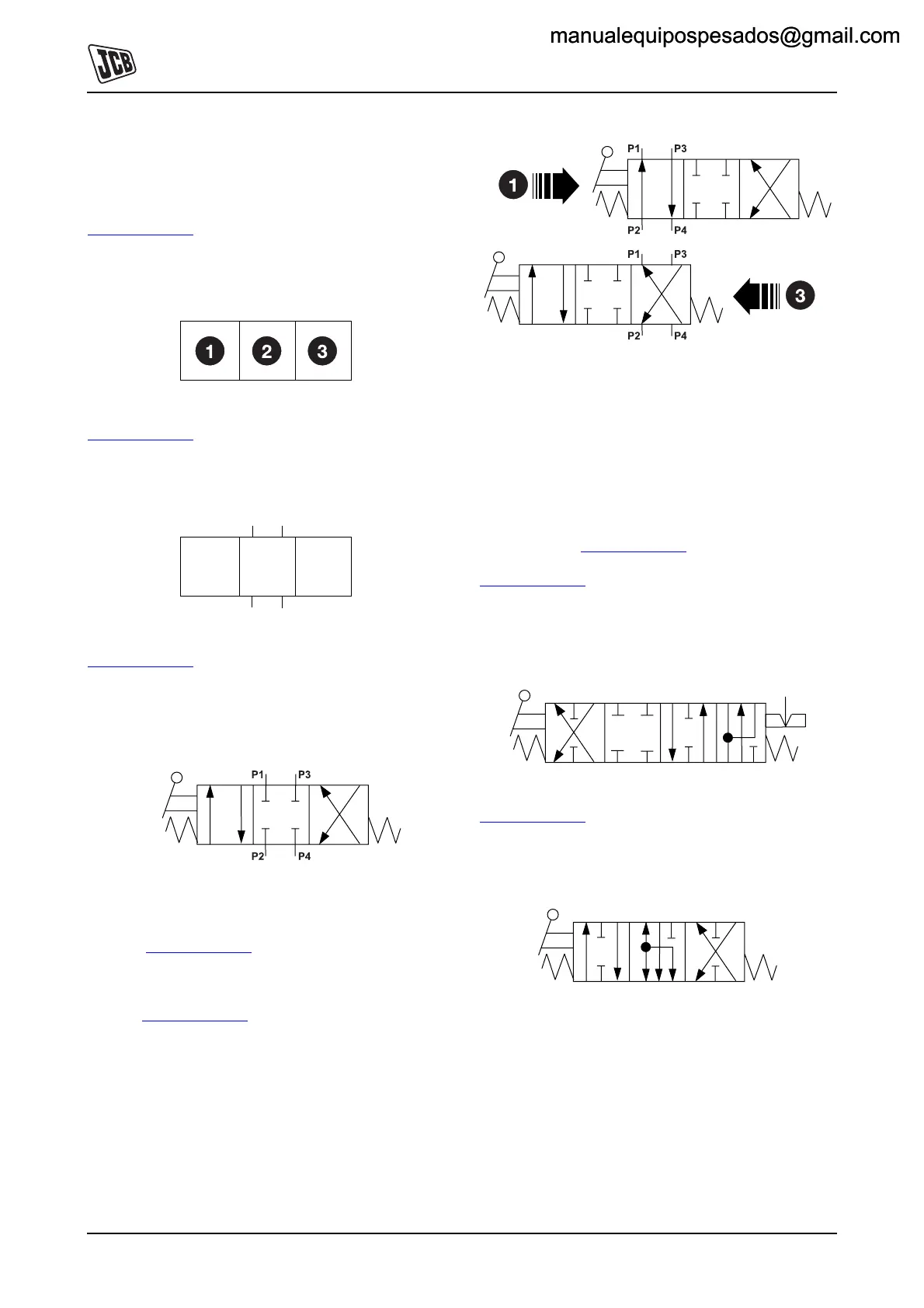
Fig 4. ( T E-7) shows a valve described as a 3-position,
4-port control valve. Port describes the openings to and
from the valve by which the hydraulic fluid enters or leaves.
In the fig shown, Position 2 indicates that in an unoperated
condition all 4 ports are blocked.
Fig 3.
If the valve spool was moved to Position 1, movement of
the spool would connect Port P1 to Port P2, and Port P3 to
Port P4. K
Fig 4. ( T E-7).
If the valve spool was moved to Position 3, movement of
the spool would connect Port P1 to Port P4, and Port P3 to
Port P2. K
Fig 4. ( T E-7).
Fig 4.
It must be noted that not all spools are of the same type.
Their operating designs can be seen by following the path
the flow arrows take in their respective operating squares.
Three typical JCB style spools are known as 'D' spools, 'F'
spools and 'N' spools.
The 'D' spools generally control rams because when in the
neutral position the outlet ports are blocked, preventing
ram movement. K
Fig 4. ( T E-7) shows a 'D' type spool.
K
Fig 5. ( T E-7) - 'F' spools are often shown as four
position spools with the three normal positions for neutral
and service control; and the forth position, which has a
detent, connects both sides of the ram together to allow the
service to 'float'.
Fig 5.
K
Fig 6. ( T E-7) - 'N' spools are sometimes used to
control hydraulic motors, and it can be seen from the flow
arrows, that in neutral position both service ports are
connected to the exhaust oil port
Fig 6.
manualequipospesados@gmail.commanualequipospesados@gmail.com
 Loading...