Section E - Hydraulics
Drive Motors
Track Drive Motor
E-27 E-27
9803-9570-4
13 Remove ‘O’ ring 11 and bearing race 12.
14 Drive out oil seal 13, using a plastic hammer, and
remove dust seal 14.
15 Remove needle bearing 15 and bearing race 16.
16 Remove output shaft 17 and retrieve balls 18.
Cleaning and checking
Wash all parts in a weak carbon based solvent.
Check all parts for wear and replace as necessary. Renew
all ‘O’ rings and seals.
Assembly
1 Place the motor housing on a clean soft surface with
the flange pointing upwards.
2 Grease the journals of output shaft 17. Position balls
18 into the holes in the shaft and assemble the shaft
into the housing.
3 Assemble new oil seal 13 and dust seal 14 into spigot
flange 10 using a suitable drift.
4 Place bearing races 12 and 16 and needle bearing 15
into the spigot flange.
5 Slip the spigot flange with assembled seals over the
shaft taking care not to damage the seals.
6 Fit the washers and screws 9 and tighten to 0.6 Nm
(0.44 lbf ft).
7 Turn the motor over so that the shaft points
downwards and place it in the assembly fixture.
8 Place a new ‘O’ ring 8 into the housing seal groove
and fit the channel plate 7.
9 Place carden shaft 6 into the drive shaft hole.
10 Fit new ‘O’ rings 8 into the seal grooves on both sides
of the gear wheel set.
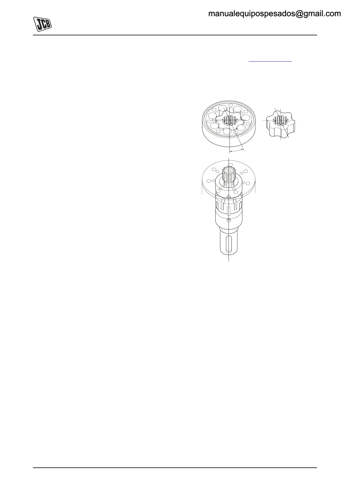
11 To ensure correct direction of rotation, place the gear
wheel set so that the axis passing through two
opposite rotor tooth profiles is at an angle of 15deg to
the axis of the key slot, K
Fig 3. ( T E-27).
The smallest diameter of the stepped bolt holes in the
gear wheel set should be positioned towards the
channel plate.
Fig 3.
12 Place end cover 4 over the gear wheel set and align
the fixing holes.
13 Fit the washers and screws 3 and tighten to 3 Nm (2.2
lbf ft).
14 Refit the drain plug and washer 2.
15 Fit the drive shaft key 1.
15º
manualequipospesados@gmail.commanualequipospesados@gmail.com

 Loading...