Section C - Electrics
Circuit Diagrams
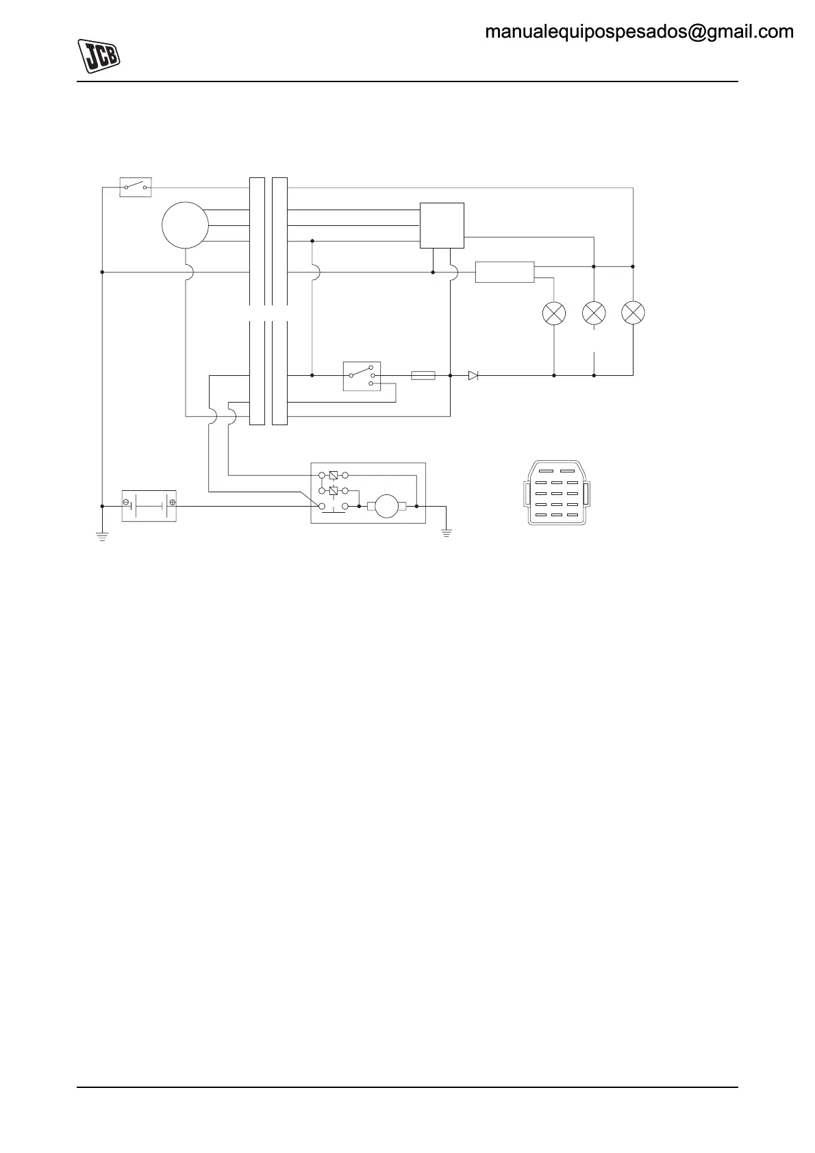
Engine Electrical Circuits
C-2 C-2
9803/9570-4
Lombardini Engine
Fig 2.
Note: Fuse item 7 is accessible by removing the cover at
the back of the starter switch box.
BATTERY
REGULATOR
15
30
50
15A
FUSE
2
M
5
IG. SWITCH
OK CIRCUIT
OK WARNING
STARTER MOTOR
OIL PRESSURE
WARNING
ALTERNATOR
WARNING
3
4
6
7
8
12
10
R
Y
Y
R
B
Y/G
SW
GRR
W
ALTERNATOR
1
OIL PRESSURE
SWITCH
9
11
CONNECTOR
4
7
1
4
14
2
5
3
MALE CONNECTOR
TERMINALS
13
1
2
3
4
5
6
7
8
910
11
12
13
14
Key
1 Oil Pressure Switch
2 Alternator
3 Battery
4 Starter Motor
5 Connector
6 Starter Switch
7 Fuse
8 Voltage Regulator
9 OK Warning Circuit
10 OK Warning Light
11 Alternator Warning Light
12 Oil pressure Warning Light
13 Male Connector Terminals
Wire Colours
RRed
YYellow
GGreen
BBlue
WWhite
Y/G Yellow/Green
SW Black
manualequipospesados@gmail.commanualequipospesados@gmail.com
 Loading...