JCB EcoMAX Engine Installation Manual
© JCB Power Systems Ltd. 320/A9164-1 Page 17 of 64
6.2 Performance
The OEM must test the exhaust system to make sure it meets performance requirements for
backpressure, vibration levels, turbocharger mounting loads (see Technical Data Sheet).
6.2.1 Backpressure
The exhaust backpressure, measured on a straight section of pipe close to the turbocharger
outlet, must be within the minimum and maximum range specified limits shown in the
Technical Data Sheet for the specific engine rating.
All exhaust backpressure figures are stated at Full Load Rated Speed and must be tested at
such condition (or as close to this point as machine controls allow). Note any additional
restriction required to meet the minimum exhaust backpressure must be fitted in the OEM
exhaust pipework downstream of the SCR components.
6.2.2 Noise Emissions
N NOTE: Exhaust systems are a significant source of off-highway equipment noise.
You must take this into account and make sure you comply with regulations.
The exhaust is a significant source of noise and can be a major contributor to the noise
emissions assessed under Directive 2005/88/EC for Equipment Used Out of Doors. You
must position the exhaust outlet and the direction in which it points carefully. You must not
install the exhaust close to the measuring positions or point it towards one of these positions.
The aftertreatment system may aid in the reduction of noise by up to 10 dBA, as a result
some machines may not need a muffler.
6.3 Exhaust Installation
C NOTICE! Never use exhaust paste upstream of the catalyst, when exhaust
paste hardens it can break off causing a hotspot on the face of the catalyst
brick and destroy it.
The Industrial Power Unit comes complete with all aftertreatment components mounted on
an isolated structure. This structure and mounting arrangement should not be disturbed or
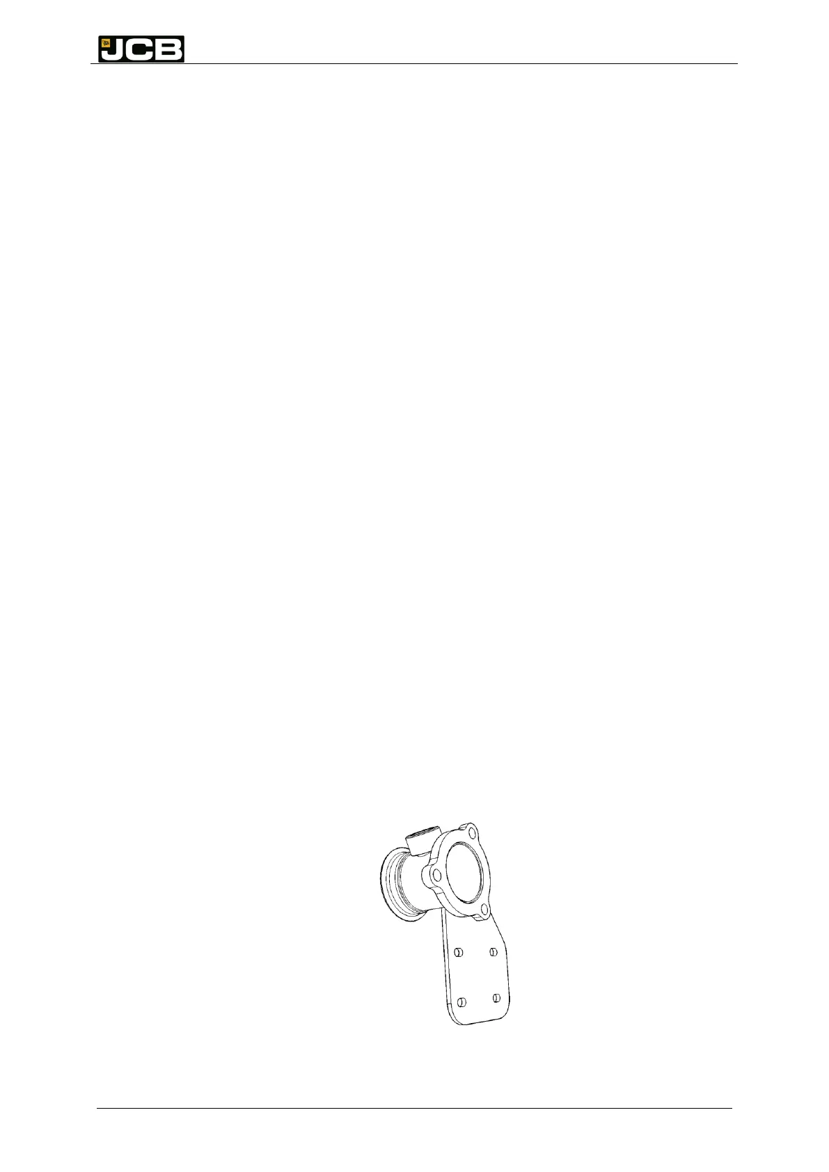
altered. A supported Stub pipe (Figure 2) has been provided which will help prevent loads
being transferred into the SCR canister; however the guidelines in this section must be
followed to ensure a successful exhaust installation is achieved. The mating flange and
gasket as supplied as part of the IPU kit of parts.
Figure 2: Exhaust mounting stub pipe