JCB EcoMAX Engine Installation Manual
Page 26 of 64 320/A9164-1 © JCB Power Systems Ltd.
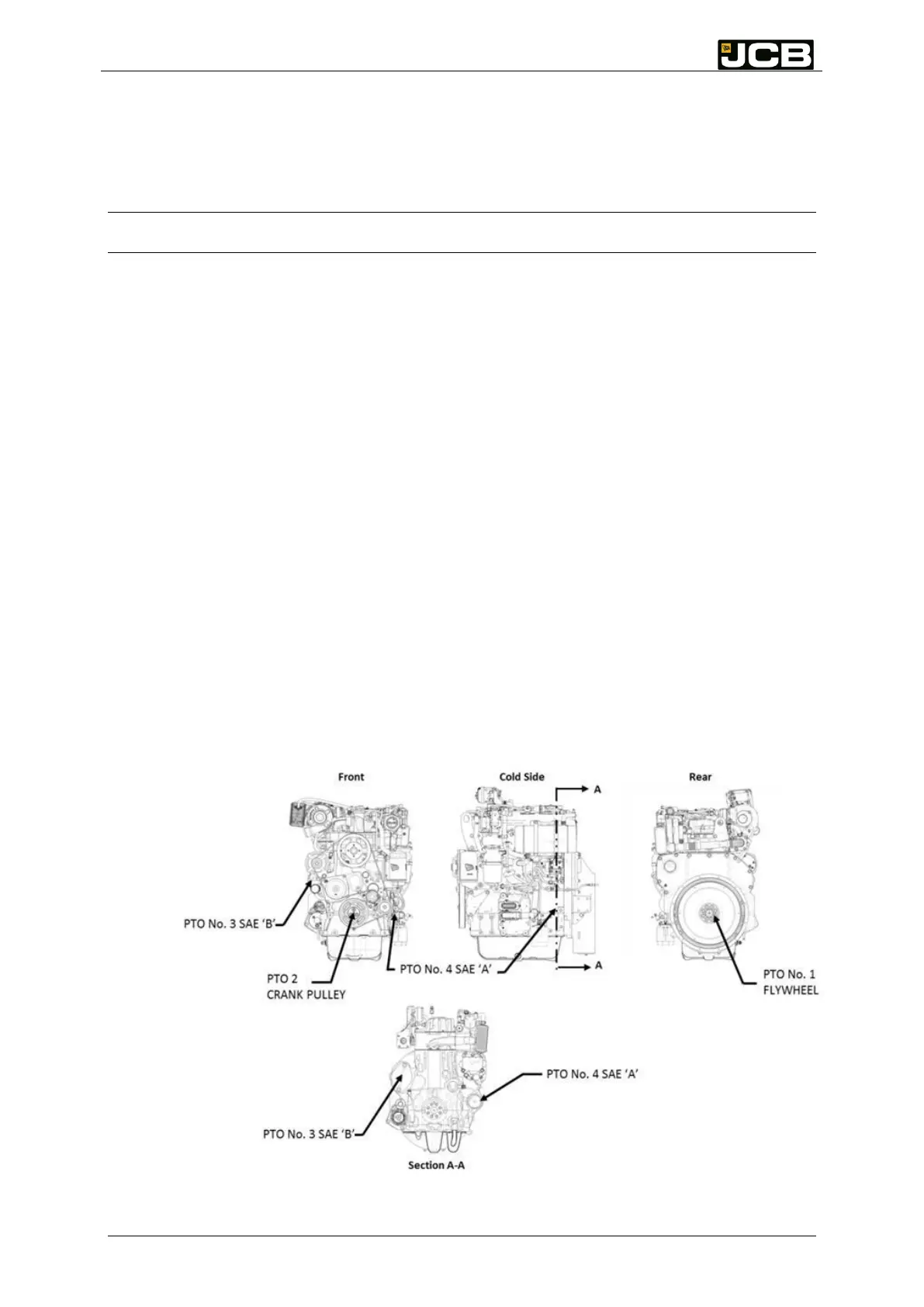
9. Power Take-Offs
9.1 Positions of Power Take Offs
W WARNING!
Operating the engine PTOs beyond their design limits may result in engine damage or personal
injury.
The four Power Take-Off (PTO) points are provided on the JCB EcoMAX engine, as shown
in Figure 4. These PTO points and maximum loadings are as follows:
PTO No. 1 – Flywheel. Full load engine torque at rated speed
PTO No. 2 – Crank Pulley. 60 kW / 260 Nm at rated engine speed (Not available
in IPU configuration)
PTO No. 3 – RHS gear case. 60 kW / 205 Nm max. at 1.268x engine speed
PTO No. 4 – LHS gear case. 15 kW / 40 Nm max. at 1.625x engine speed
PTO No. 3 & PTO No. 4 are mounted to the gear casing by two-bolt flanges to the SAE
standard J744 pattern. PTO No. 3 conforms to the SAE B standard, while PTO No. 4
conforms to the SAE A standard. A four bolt-boss has been provided on the cylinder block
adjacent to PTO No. 3 to allow for supplementary support brackets if required, as shown in
Figure 5. Devices attached to both PTO No. 3 and PTO No. 4 must carry their own gears.
For gear details please contact JCB Power Systems Applications department.
PTOs operate in the anti-clockwise direction when viewed from the rear of the engine.
A flange to SAE standard J1946 (size code 1410, Type S) is provided on the crank nose for
provision of PTO No. 2.
The alternator is direct mounted to the RHS of the engine and driven by the FEAD system.
Provision has been made for the direct mounting of an air-conditioning compressor to the
lower LHS of the engine. The FEAD is capable of driving this type of compressor.