JCB EcoMAX Engine Installation Manual
Page 58 of 64 320/A9164-1 © JCB Power Systems Ltd.
- Have records available for inspection by either EU and/or EPA/CARB as appropriate for the end
destination of the machines being assembled.
If further clarification of the exact requirements is required please contact JCB Power
Systems.
18.5 Fitting Engine Covers or Installing items to the gear driven
PTO’s
JCB engines are supplied to a level of assembly which provides maximum flexibility to the OEM
installer with minimum need to alter other components. In most cases the gear driven PTO’s are
supplied with bolted covers in place of the PTO unit. Sealing of PTO units is typically achieved by O-
ring, meaning that gaskets would not be required. However this is not always the case and the OEM
Manufacturing Engineer should check with their Design department.
It is important to ensure that any cap or PTO device is fully inserted prior to tightening fasteners. The
bolts should be of the appropriate grade and torqued to an agreed standard. It is strongly
recommended that flanged bolts are used, but failing that bolts and plain washers are required to
avoid galling of the bolt head into the material of the cover or PTO device.
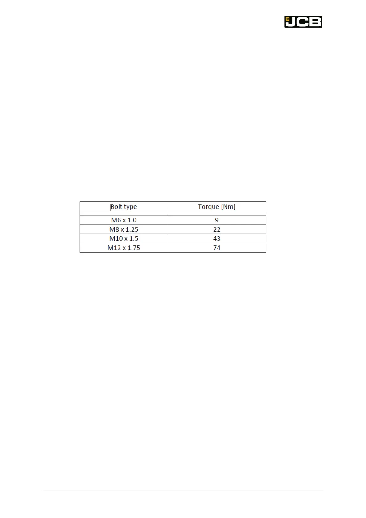
JCB recommend that the Design office of the OEM verify the required tightening torque by completing
their bolted joint calculations. If 8.8 bolts are used, dry, with zinc plating, JCB would use the nominal
torque laid out in Table 5.1.
Table 5.1: Nominal tightening torques for dry assembly of zinc plated grade 8.8 bolts
18.6 DEF and Fuel System Cleanliness / capping
Optical sensors such as used in the Adblue header unit must be maintained in a manner so as to keep
them free from dust or grease.( Including avoidance of fingerprints on the optical unit)
18.6.1 DEF and Fuel tanks
Diesel fuel and DEF injection systems are complex in a number of ways. It is important to ensure that
both the tanks and fluids are properly prepared so as to minimise the risk of early life failures.
All fuel and DEF system components, including liquid storage tanks, should be kept clean and dry.
Diesel tanks should be oiled internally if not painted or otherwise coated to protect them from build-
up of rust. Both diesel and DEF tanks should be clean at manufacture and capped until such time as
they are installed in the machine.
18.7 Assembly Best Practice
This section is intended to provide some insight into JCB Power Systems assembly process, in
anticipation that parallels can be drawn by the customer Manufacturing Engineer.
JCB’s approach is fundamentally as follows:
To ensure reliability of the engine and installation it is in the interests of both JCB and the engine
installer to have some common ground on assembly techniques.
“No faults forward”; the engine will pass through further stations to a rework area if an issue
is identified during assembly
Components assembled on an Operation by Operation basis, with suitable dunnage used to
store parts next to the assembly line.
Where an Operation requires a choice in components, those components will be bar coded
so that the correct part is scanned and fitted.