JCB EcoMAX Engine Installation Manual
© JCB Power Systems Ltd. 320/A9164-1 Page 27 of 64
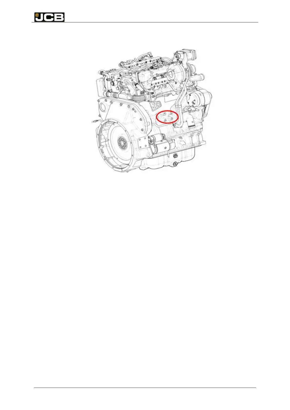
Figure 4: Positions of Power Take-Offs
Figure 5: Supplementary support bosses
9.2 Performance of Power Take Offs
You must make the following considerations about the PTOs:
PTO No. 1 loading with belt or chain drive
PTO No. 2 maximum unsupported weight and bending moment
PTO No. 3 & PTO No. 4 Pump efficiency ( mechanical and hydraulic) , duty cycle
of PTO pump, relief valve setting and location must be reviewed to ensure gears
are not overloaded. As well as the mass and supporting of the pump.
You must make sure that, in common with all other structures attached to the engine, the
PTO-driven device has a primary resonant frequency greater than 150 Hz. Bosses have
been provided at various positions on the engine (see Figure 5) to which you can attach
additional support brackets, if necessary.
PTO No. 3 has been evaluated successfully with cast iron hydraulic pumps with no additional
support and a calculated bending moment of up to 33 Nm.
Please consult JCB Power Systems Applications department for specific information and
advice.