JCB EcoMAX Engine Installation Manual
© JCB Power Systems Ltd. 320/A9164-1 Page 33 of 64
12.4 Electromagnetic Compatibility
Electromagnetic emissions for the electrical system of the machine must be tested when it is
applicable to the application.
N NOTE: It is the manufacturers’ responsibility to make sure that the machine
conforms to the overall EMC limit.
12.5 Cold Start Strategy
The grid heater (when supplied) is located in an aperture in the inlet manifold. Its use
depends upon ambient temperature and available cranking speed in the machine. The
control of the heater is done by the engine ECU which automatically activates it when
required.
Sometimes it may be beneficial for the grid heater to stay energised whilst cranking. Some
post heat (after start) will occur automatically under severe cold conditions.
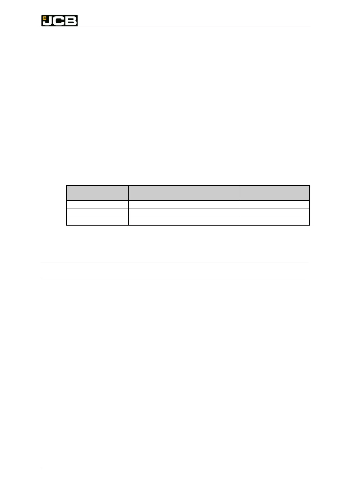
Table 4: Cold start strategies
Mean crank speed
required (rpm)
Block heater plus grid heater
12.6 Battery
W WARNING!
You must always remove the negative battery lead before you do any work on the equipment or
engine. You must also make sure that all appropriate warnings, and or, labels advise accordingly.
Use only one battery for 12 V systems. You need two batteries for 24 V systems. Each
battery must have a minimum rating of 900 CCA (SAE) / 145 Ahr.
12.6.1 Installation
You must support the battery or batteries on a carrier that holds the battery flat and level
under normal load conditions. The battery carrier must have sufficient strength to hold the
battery in place under all conceivable conditions, including equipment roll over. Make the
bracket sufficiently stiff that it does not suffer from significant resonant vibration under normal
operating conditions.
It is important that the battery compartment is open to the atmosphere to avoid a build-up of
dangerous gases. You can improve the battery performance and life by protecting it from
large variations in temperature (either excessive heat or excessive cold). The battery
temperature must stay below 50°C at all times. Take account of maintenance of the batteries
when you design and locate the battery carrier.
12.6.2 Earthing
The negative terminal of the battery must be earthed to the main chassis (through a battery
isolator, where required). Earth leads must be kept as short as possible and have a minimum
cross-sectional area of 95 mm
2
for a 12 volts system and 70 mm
2
for a 24 volts system.