13
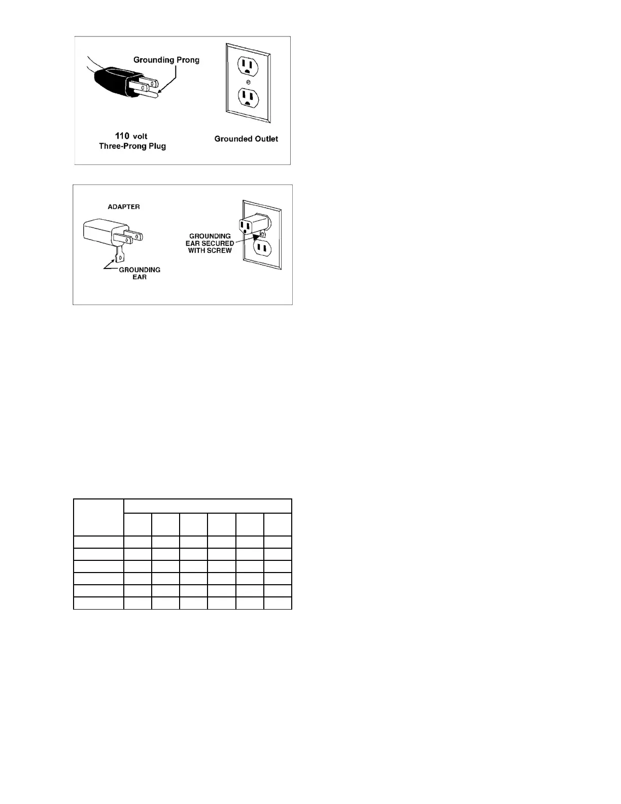
Figure 7-1
Figure 7-2
7.2 Extension cords
The use of extension cords is discouraged; try to
position machines near the power source. If an
extension cord is necessary, make sure it is in good
condition. When using an extension cord, be sure to
use one heavy enough to carry the current your
product will draw. An undersized cord will cause a
drop in line voltage resulting in loss of power and
overheating. Table 2 shows correct size to use
depending on cord length and nameplate ampere
rating. If in doubt, use the next heavier gauge. The
smaller the gauge number, the heavier the cord.
Recommended Gauges (AWG) of Extension Cords
Amps
Extension Cord Length *
25
feet
50
feet
75
feet
100
feet
150
feet
200
feet
< 5 16 16 16 14 12 12
5 to 8 16 16 14 12 10 NR
8 to 12 14 14 12 10 NR NR
12 to 15 12 12 10 10 NR NR
15 to 20 10 10 10 NR NR NR
21 to 30 10 NR NR NR NR NR
*basedonlimitingthelinevoltagedropto5Vat150%oftherated
amperes.NR:NotRecommended.
Table 2
8.0 Adjustments
8.1 Drum Height Control
Drum height and depth of cut are controlled by
height adjustment handle (B, Figure 6-3). Rotating
handle clockwise lowers drum, counterclockwise
raises it. One revolution of handle will move drum
approximately 1/16” (or 1/4 turn = approx. 1/64”), as
shown on label below handle.
8.2 Depth scale
The depth scale indicates distance between bottom
of sanding drum and top of conveyor belt.
Adjustment is performed by “zeroing” the scale.
1. Unplug sander from power source.
2. With an abrasive strip on drum, lower drum to
where it just contacts top of conveyor belt. Note:
Make sure drum – not just tension rollers –
contacts conveyor belt.
3. At this drum position, the depth scale pointer
should align with zero mark on scale. If it does
not, loosen two screws on scale and adjust
scale until zero aligns with the pointer.
4. Retighten screws.
Depending on desired accuracy, you may need to
repeat this process when installing different
abrasive grits.
8.3 Depth stop assembly
(OPTIONAL)
NOTE: The depth stop assembly is optional for
JWDS-2244, but included with JWDS-2550.
The depth stop nut (A, Figure 1) provides a hard
stop at final sanding depth. It ensures that the
operator will not sand too deeply when he/she
wishes to make multiple pieces the same final
thickness.
1. Rotate handle to position drum at final sanding
depth according to scale. (Figure 8-1 shows
7/8-inch final depth as example).
2. Press button on stop nut to slide nut into general
position, then rotate nut until it firmly contacts
bottom of plate (B).
CAUTION: The stop nut is designed to be used
below the plate to allow full support when nut
contacts plate. Using it above the plate may
cause deflection as nut pushes into it.
3. Raise drum and perform sanding operation.
Depending on the workpiece, multiple passes
may be needed until final depth is reached and
stop nut is contacted.
If stop assembly will not be used, loosen left screw
(C) and rotate plate (B) out of the way (see inset).
This allows free drum movement.