57
TwinForce™ Series Waterblast Unit
Note: On 40K uid ends, the brass
sleeve (Figure 91) inside the
stufng box does not need to
be removed unless the plunger
shows evidence of rubbing on the
sleeve.
11. Remove the O-ring (Figure 92) from the
gland nut.
12. Repeat the previous steps for the remain-
ing stufng boxes if packing is to be
replaced.
Inspection
1. Inspect the plunger for scratched or deep
scores. Discard damaged plungers.
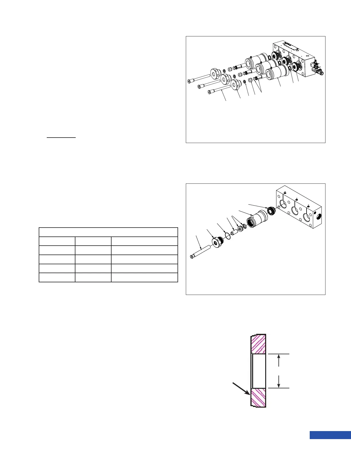
2. On 40K units, measure the diameter of
the guide bushing (Figure 93, A). If the
diameter exceeds the Dimension A speci-
cation listed in the “40K Guide Bushing
Replacement Table” below, replace the
bushing. If the bushing shows scoring or
if the edge is chipped, replace the bush-
ing.
40K Guide Bushing Replacement Diameter
Fluid End Plunger Size Dimension A
3040 # 5 0.533 in. (13.54 mm)
3640 # 6 0.603 in. (15.32 mm)
4240 # 7 0.673 in. (17.09 mm)
4240 # 8 0.733 in. (18.62 mm)
1
2
3
4
5
6
7
1. Plunger
2. Gland Nut
3. O-Ring
4. Guide Bushing
5. Packing
6. Stufng Box
7. Uni-Valve
Figure 91: 15K/20K Fluid End (Some Components Not Shown).
Figure 93: Guide Bushing Check (40K Only).
This side into
gland nut
A
Figure 92: 40K Fluid End (Some Components Not Shown).
1
8
7
6
5
4
3
2
1. Plunger
2. Gland Nut
3. Guide Bushing
4. Packing
5. Brass Sleeve w/ O-Ring
6. Stufng Box
7. Face Seal
8. Uni-Valve