210.100-IOM (JUL 2021)
Page 15
AcuAir Hygienic Air Units
Installation
Performance Grade connections
Reassembling split unit,
Performance Series only
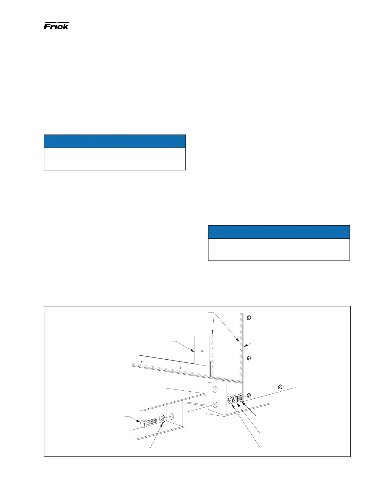
1. Position sections on level surface.
2. Apply polyurethane caulk in two parallel continuous
beads on both faces as indicated in Figure 9, to Figure
11.
3. Attach hand winches to either side of the base using
relocated lifting lugs and pull the sections together.
Bolt base as shown in Figure 9.
NOTICE
It may be advantageous to locate the rst section in
it's nal position and attach it to the support struc-
ture before pulling the next section into position.
4. Install the reconnect ange attachment hardware
starting from the middle of the bottom angle working
around to the middle of the top angle, making use of a
drift pin to align the holes. Bar clamps may be needed
to align the roofs together. If bar clamps are needed,
use wood for protection in between the bar clamp and
unit.
5. Split seams that have internal access to both sides of
split are reattached with bolts and nuts. Split seams
with internal access to only one side of split have cage
nuts on the blind side and bolts installed from acces-
sible side. All bolt holes require a bolt.
6. If bolt holes do not align, it may be due to racking
during transit to job site. Use jack to lift one side until
holes on the wall of the opposite side align. Bolt this
wall together and then remove jack from opposite side.
As the unit settles, the out-of-square racking caused
during transit realigns.
7. After the sections are drawn together and the recon-
nect anges are aligned and attached, apply two paral-
lel beads of caulk along either side of the reconnect
seam on the exterior of the AcuAir
®
unit as shown in
Figure 13.
8. Install the shipping split covers as shown in Figure 13
using the #10 TEK screws and washers provided. Apply
a ne bead of caulk to either edge of the split cover and
allow time to dry.
9. After the shipping cover is in place and the caulk has
had time to set, apply the roof coating as shown in
Figure 14.
10. Inspect all splits to see if polyurethane caulk was ap-
plied and split was bolted correctly.
11. Reconnect all electrical conduit and wiring at the re-
connect junction boxes. Use electrical conduit sealing
putty to seal all conduit openings into and out of the
junction box to prevent the migration of moisture.
12. Inspect all splits to see if all electrical and piping con-
nections are complete and correct.
NOTICE
Do not remove temporary roof supports and diagonal
(shipping) supports until the split sections are com-
pletely reassembled. See Food Grade connections.
INTERNAL RECONNECT
(AcuAir Performance Series Only)
.75 FLATWASHER
.75 HEX BOLT
(USE FROM LIFTING LUG)
.75 HEX NUT
(USE FROM LIFTING LUG)
.75 SPLIT WASHER
.75 FLAT WASHER
.25 MINIMUM DIA. PARALLEL CONTINUOUS BEADS OF
POLYURETHANE CAULKING REQ’D (BOTH FACES OF SPLIT)
PRIOR TO REASSEMBLING
RECONNECT, HOUSING, AND
HARDWARE NOT SHOWN THIS SIDE
FOR CLARITY
HOUSING
Figure 9: Base assembly attachment - relates to AcuAir Performance Series unit only

 Loading...


