210.100-IOM (JUL 2021)
Page 14
AcuAir Hygienic Air Units
Installation
Section reconnect ship loose items
• Acu-Shield roof coating
• Joint sealing caulk
• Seal gasket tape
• 1/4 in. bolts and nuts
• Electrical conduit sealing putty
Installation tools
To complete the installation of an AcuAir
®
system, the fol-
lowing tools are required:
• Drift pins
• 8 ft straight edge
• Level
• Assorted open-end wrenches
• Socket set
• Caulk gun
• Tape measure
• Chain falls
• Screw gun with nut drivers
• Paint brush or roller for applying Acu-Shield roof
coating
Assembling roof curb (optional)
1. When supplied by Johnson Controls - AcuAir
®
, roof
curbs ship either fully welded or in pieces. If bolted
curb construction, bolt together.
2. Curb must be level (shim if required). Place shims, at
fractions of an inch, at intervals no greater than 5 ft
apart. Shims are not intended to compensate for roof
pitch. Individual stacks of shims must not exceed 1/2 in.
in height. On large units with splits, remember to shim
at the split’s midspan. See Figure 8.
3. The installer is responsible to secure the roof curb to
the building structural support in accordance with local
codes.
4. Seal all roof curb joints and seams with a suitable
sealer or polyurethane caulk to prevent water leakage.
Installing roof curb
1. Verify that the curb is level and secured to the roof.
2. Verify that there is adequate height between the base
of the unit and the roof to allow for drain trapping.
3. Install a 1/8 in. thick neoprene gasket on the top of
the curb to provide a seal between the unit and the
roof curb. If the unit or unit sections must be slid into
place, a polyurethane sealant may be used in lieu of the
gasket.
4. Lift the unit in place.
5. The installer is responsible to secure installation in ac-
cordance with the local codes.
General split unit reassembly
Units that are shipped in sections, must be installed on an
appropriate foundation and carefully assembled to provide
the required unit performance.
• AcuAir
®
units must be level for reassembly.
• All bolts, nuts, washers, split covers and polyurethane
caulking (if required) can be found in supply fan sec-
tion.
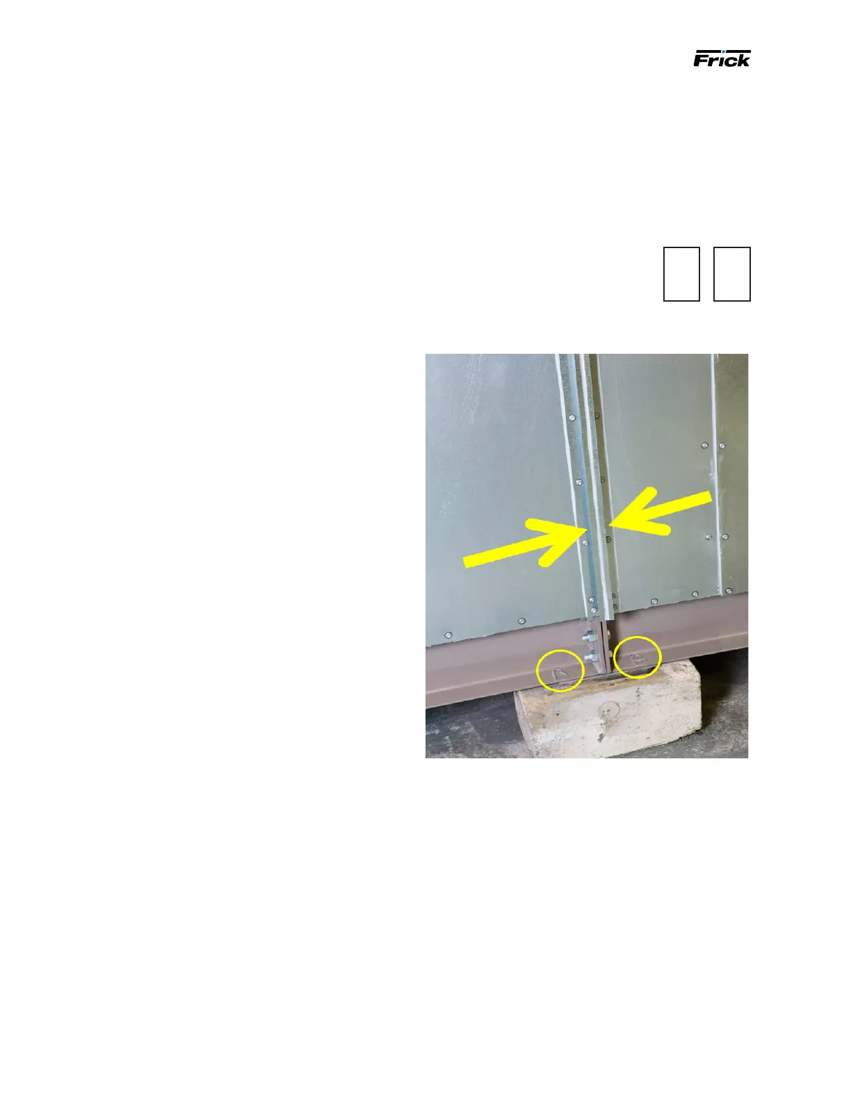
• All splits are identied with welded
letters on the base channel (A-A,
B-B, for example) to indicate which
sections are to match up for reas-
sembly.
Figure 8: Food grade unit reconnection
Removable lifting lugs
You are provided with removable lifting lugs along either
the width or length of the various sections of the unit.
Lifting lugs may be repositioned before lifting. After the
sections have been placed as close as possible to each
other, remove any lifting lugs in the reconnect split. You
can use a hand-actuated winch or a come-along to bring
the unit sections together for nal bolting. Attach the hand
winch or come-along to each side of the base using the
lifting lugs relocated to the alternate side locations and
draw the sections together.
Electrical wiring and piping
It is the installer’s responsibility to reconnect all internal
and external electrical or piping splits. All wires are col-
ored or numbered to designate which wires to join at each
split. Before turning on power, check all electrical circuits
for continuity.
MATCH
A
→
MATCH
A
←

 Loading...


