210.100-IOM (JUL 2021)
Page 23
AcuAir Hygienic Air Units
Installation
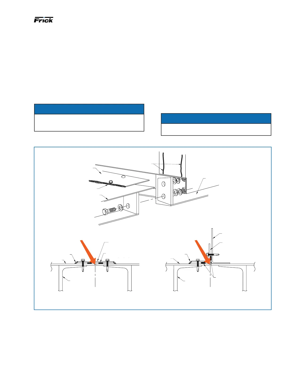
Insulating the base reconnect seam
of an AcuAir Food Grade Series unit
When two AcuAir
®
unit sections are drawn together the
base channels of the two sections form an uninsulated
cavity that under certain conditions could produce con-
densation. AcuAir
®
provides a ship loose foam insulation
kit to ll this cavity as part of the reconnect procedure.
The insulation may be injected either from the top of the
cavity before installing the reconnect split cover strip, or
from underneath the unit provided the reconnect joint
is not positioned directly over a support structure cross
member.
NOTICE
Inject the foam into this open seam after the
sections are joined and before the seam cover is
installed.
BASE CHANNEL
SPLIT COVER
BASE SKIN
CAULK EDGE OF COVER
AFTER ANCHORING
CAULK
BASE
CHANNEL
SPLIT COVER
CAULK
BASE SKIN
C
L
SPLIT
.25" DIA CONTINUOUS
BEAD OF CAULK
TYP JOINT OF TWO SECTIONS WITH FLAT SURFACES
Inject Foam Prior to
Installing Cover
CAULK
BASE SKIN
BASE
CHANNEL
INTERNALWALL
FINISH BEAD
OF CAULK
C
L
SPLIT
SIDE VIEW WHEN INTERNAL WALL IS AT A SPLIT
Inject Foam Prior to
Installing Cover
SPLIT COVER
Follow the instructions provided by the foam manufac-
turer for preparing the two part foam mixture and the
injection kit. Take special note of the 30 s inactivity limit,
after which the injection nozzle may become permanently
clogged.
Inject foam into the cavity at a rate of 3 brd-ft to 4 brd-ft
for each linear ft of seam. This means a 15 brd-ft can of
expanding foam lls between 4 ft to 5 ft (linear) of AcuAir
®
reconnect seam.
When lling the reconnect seam from the top, inside the
AcuAir
®
unit, it may be advisable to cover the bottom
of the opening with duct tape to prevent the foam from
dropping out before it has a chance to expand and attach
itself to the cavity walls.
NOTICE
If foam dispensing has stopped for more than 30 sec-
onds, replace the nozzle with the extra provided.
Figure 19: Insulation of the base reconnect seam
0.25 IN. DIA CONTINUOUS
BEAD OF CAULK

 Loading...


