210.100-IOM (JUL 2021)
Page 11
AcuAir Hygienic Air Units
Installation
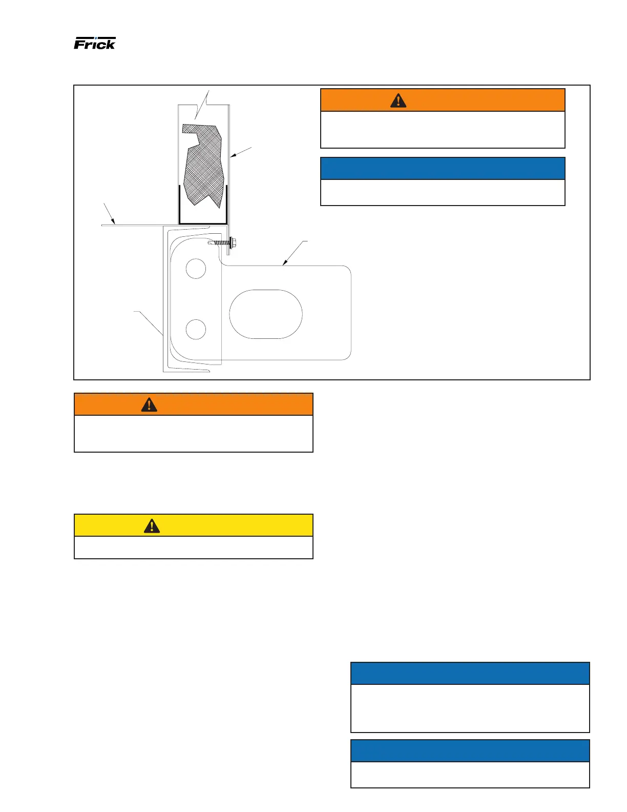
Figure 5: Lifting lugs
WARNING
Do not lift non-base units or subassembly by attach-
ing clevis hooks, pins or bolts to casing, casing hard-
ware, angles, tabs or anges.
LD07923A
HOUSING
BASE SKIN
LIFTING LUG
PERIMETER
CHANNEL
WARNING
When lifting; use all lifting lugs to avoid damage
and/or personal injury. Lifting lugs are shown in
Figure 5.
Do not lift non-base units or subassemblies by attaching
clevis, hooks, pins, bolts or other related components to
casing, casing hardware, angles, tabs, or anges. Lift the
air unit only in an upright position. Never lift or move a
unit on its side or upside-down.
CAUTION
If you do not rig or lift the unit carefully, you could
damage the unit, hurt yourself or others.
Support structure information
AcuAir
®
systems may be shipped in two or more sections.
These sections must be anchored to a suitable support
structure - concrete pads, concrete piers, or structural
steel, capable of supporting the total system operating
weight plus a signicant safety margin as determined by
a qualied structural engineer. The weight the support
structure must support and the anchoring requirements
varies with live loads (expected snow or ice buildup)
seismic, and wind loading. See Figure 6 and Figure 7 for
AcuAir
®
unit support methods.
If the support structure is in the form of two or more
parallel steel beams, size the beams in accordance with
standard engineering practices. The structure must be
capable of supporting the shipping weight of the unit as
provided on the order related document, plus any operat-
ing-duty-related loads such as: water or refrigerant within
the cooling and heating coils; possible frost on the cooling
coils; any applicable ooded refrigerant surge vessel and
associated piping; snow loads that could accumulate on
the roof; horizontal wind loads.
Frick suggests designing the structure for at least 110% of the
operating weight of the system to be distributed as a uniform
load over the longitudinal beams, allowing for a maximum
deection of 1/360 of the length, not to exceed 1/2 in.
The support structure, whether concrete pads, concrete
piers, or structural steel, on which the units are to be
located must be rigid and level (shim if required).
Place shims at intervals no greater than 5 ft apart. Do not
use shims to compensate for signicant surface slope. The
sum total of any individual stack of shims must not exceed
1/2 in. and are to be used to compensate for surface
irregularities only. On units more than 150 in. wide the
foundation can support not only the perimeter base chan-
nel, but also the midpoint of each unit split. See Figure 6.
Consult factory if housekeeping pad is not continuous.
The AcuAir
®
unit must be secured to the support struc-
ture. It is the installer’s responsibility to be sure the unit is
secured in accordance with applicable codes.
NOTICE
Shims may be used between the AcuAir
®
unit and the
supporting structure. When using shims, space them
no more than 5 ft apart. Shim stacks must not exceed
1/2 in. in height.
NOTICE
Units must usually be slid into nal position. Applying
grease to the support surface can make this easier.
NOTICE
Save bolts when removing lifting lugs. Bolts are used
for assembly of split units.

 Loading...


