210.100-IOM (JUL 2021)
Page 26
AcuAir Hygienic Air Units
Installation
Figure 27: Plenum leg attachment
9. When the plenum is plumb and level, use the screws
that were provided to attach the plenum section to the
AcuAir
®
unit. The screws are shipped loose and can
be found in the blower section. The predrilled holes
indicated in the plenum frame show the location and
number of attachment points required. The plenum as-
sembly must be securely screwed to the unit.
10. Replace the access panel, ensuring that all screws are
in place.
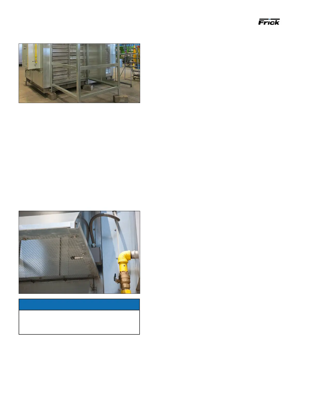
11. When a set of detached hoods is shipped separately,
one hood requires a 1 in. hole in the side for mount-
ing the fresh air temperature sensor. Locate the hood
nearest the sensor and electrical ex conduit. Drill a 1
in. hole and insert the sensor conduit probe and secure
the j-box to hold the assembly in position. See the fol-
lowing gure.
Figure 28: Fresh air temperature sensor mounting
NOTICE
Any penetration of cabinet skin causes water and
air leakage. Thoroughly seal any screw, piping or
electrical holes with appropriate sealant. Self tapping
screws are not weathertight.

 Loading...


