RWF II ROTARY SCREW COMPRESSOR UNITS
OPERATION
070.610-IOM (JUN 11)
Page 20
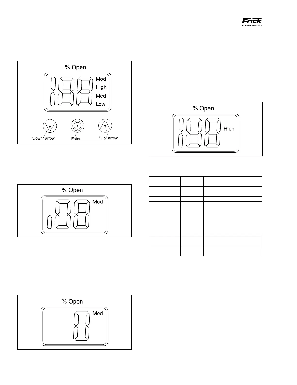
• “Down” arrow push button (Figure 22)
Decreases parameter number by 1 at each activation
• “Up” arrow push button (Figure 22)
Increases parameter number by 1 at each activation
Figure 23
• Enter push button (Figure 22)
Gives access to the Parameter list by keeping the push
button activated for 2 seconds. A Parameter list example
is shown below (parameter
i
08, Figure 24).
Gives access to change a value once the Parameter list
has been accessed.
Figure 24
Acknowledge and save change of value of a parameter.
To exit from the Parameter list and return to the display
of Opening Degree (OD), keep the push button activated
for 2 seconds.
• Display (Figure 22)
Normally the Opening Degree (OD) 0 100% of the ICM
valve is displayed. No activation of push buttons for 20
seconds means that the display will always show OD
(Figure 25).
Figure 25
• Displays the parameter.
• Displays the actual value of a parameter.
• Displays the function status by means of text (Figure 22).
Mod represents that ICAD is positioning the ICM valve
according to an analog input signal (Current or Voltage).
Low represents that ICAD is operating the ICM valve like
an ON/OFF solenoid valve with low speed according to
a digital input signal.
Med represents that ICAD is operating the ICM valve like
an ON/OFF solenoid valve with medium speed according
to a digital Input signal.
High represents that ICAD is operating the ICM valve like
an ON/OFF solenoid valve with high speed according to
a digital input signal (Figure 26).
Figure 26
Alarms - ICAD can handle and display different alarms.
Description
ICM
Alarm Text
Comments
No valve type
Selected
A1
At startup A1 and
CA will be
displayed
Controller fault A2 Internal fault inside electronics
All input error A3
Not active if
i
01
= 2 or
i
02
= 2
When
i
03 = 1 and AI A > 22 mA
When
i
03 = 2 and AI A > 22 mA
Or Al A < 2mA
When
i
03
= 3 and AI A > 12V
When
i
03 = 4 and Al A > 12V or
Al A < 1 V
LOW voltage of
failsafe supply
A4 If 5 V d.c. < Failsafe supply
< 18 V d.c.
Check Supply
to ICAD
A5 If supply voltage < 18 V d.c.
If an alarm has been detected the ICAD display (Figure 22)
will alternate between showing Actual alarm and present
Opening Degree.
If more than one alarm is active at the same time, the alarm
with the highest priority will take preference. A1 has the
highest priority, A5 the lowest.
Any active alarm will activate the Common Digital Alarm
output (Normally Open).
All alarms will automatically reset themselves when they
physically disappear.
Old alarms (alarms that have been active, but have physically
disappeared again) can be found in parameter
i
11.
Reset to factory setting:
1. Remove the power supply.
2. Activate down arrow and up arrow push buttons at the
same time.