20 Hardware Installation—IFC-200 Hardware Installation Procedures
T
B
6
A B B+ A+ B- A-
M500XJ
Isolator Module
M500XJ
Isolator Module
M500XJ
Isolator Module
M500XJ
Isolator Module
Protected
Premises
Area "1"
Protected
Premises
Area "3"
Protected Premises Area "2"
4wcl_2
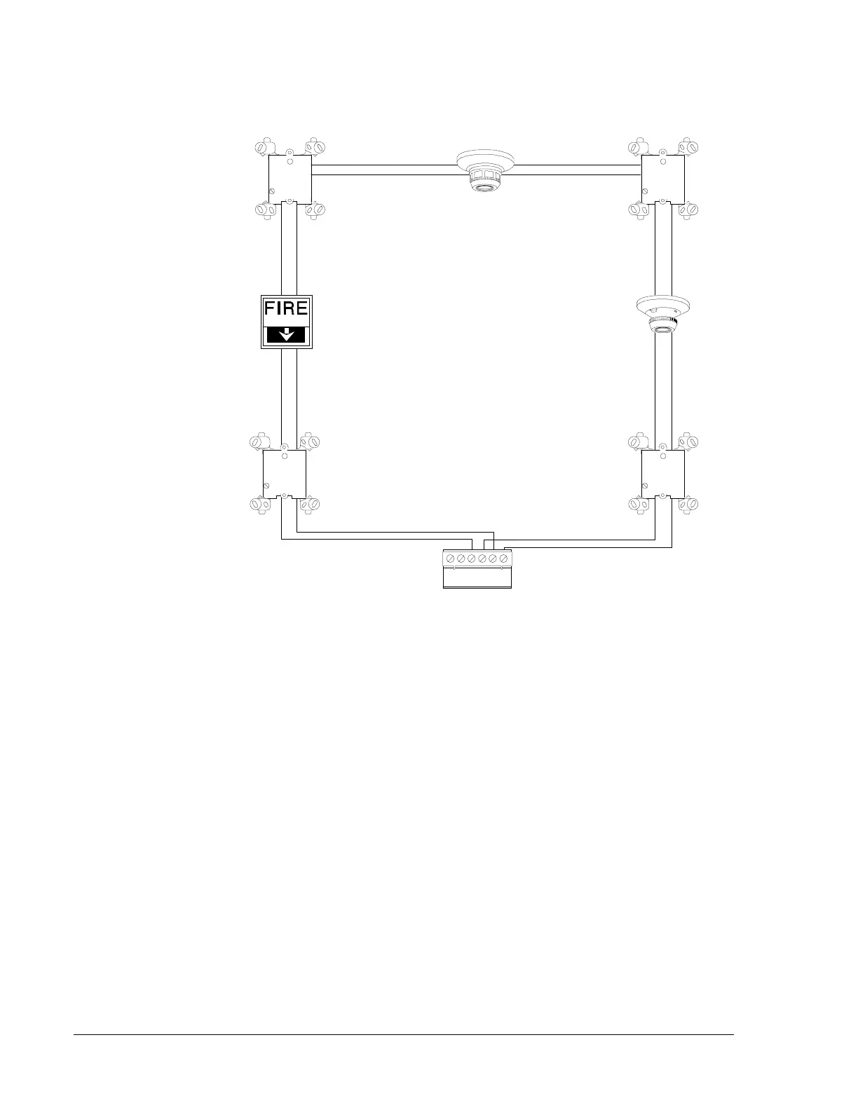
Connect SLC + OUT to TB6 B+ and SLC - OUT to TB6 B-
Connect SLC + OUT to TB6 A+ and SLC - OUT to TB6 A-
Optional
Optional
Optional
Optional
IFC-200
Figure 12: Four-Wire, Style 7 Communications Loop
By flanking a group (zone) of devices on the SLC with a pair of M500XJ
fault isolator modules, each area is protected from a short circuit fault on
another area. When a short circuit occurs in one area, the M500XJ on
either end of that section of the SLC will open the SLC, thus allowing the
other addressable devices on the SLC to continue to communicate. For
example, a fault on Area 2 will not affect Areas 1 and 3. The isolator
modules on either side of Area 2 will open the loop. Area 1 will still
operate from power on Loop Out, and Area 3 will operate from Loop
Return. Since the IFC-200 will no longer be able to communicate with
Area 2, a trouble signal(s) will be generated for those devices (Invalid
Reply error messages). The Style 7 circuit does not allow T-tapping or
branching, and the ratings and characteristics for this circuit are the same
as for a four-wire circuit meeting NFPA Style 6 requirements. It is
recommended that no more than 30 addressable devices be located
between any pair of isolator modules.
Isolator Module
Operation
 Loading...

