40 Hardware Installation—IFC-200 Hardware Installation Procedures
Operation
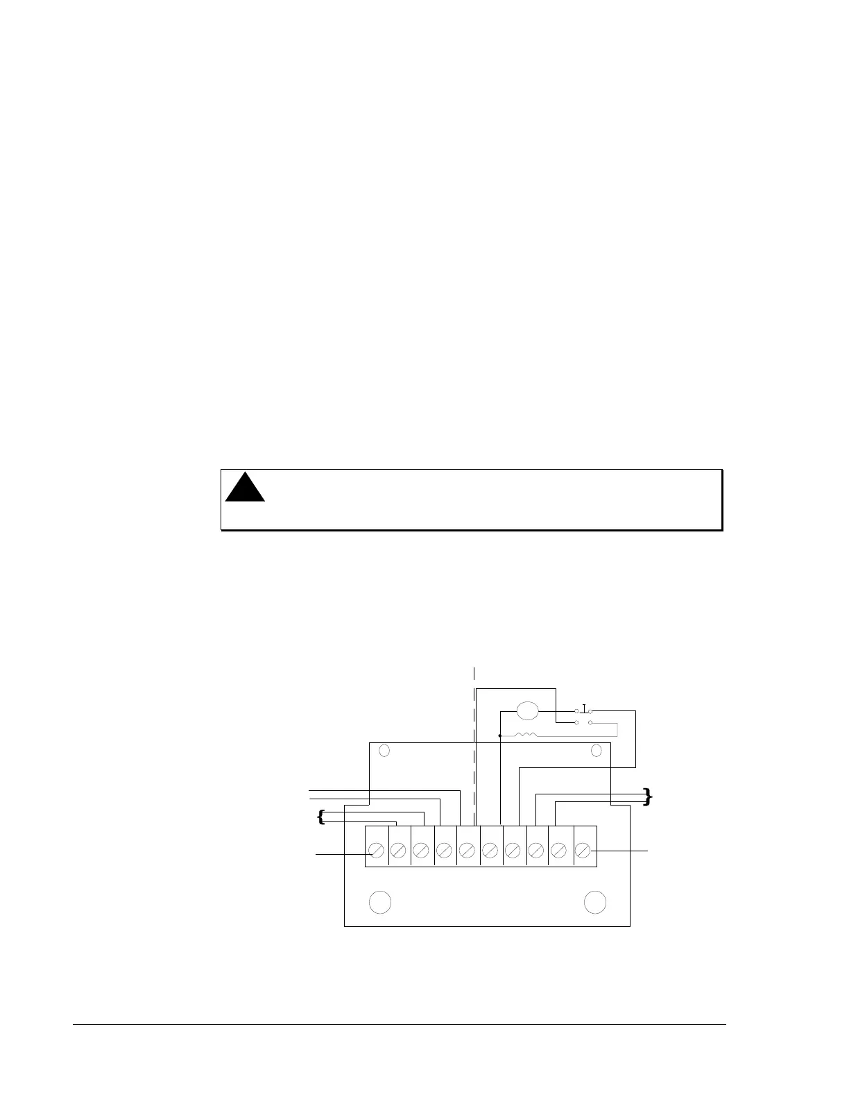
1. Connect 120 VAC to terminals 1 and 2. The AC pilot light comes on.
The voltmeter indicates the charger output.
2. Connect the battery, positive to terminal 3, negative to terminal 4.
Charging current starts automatically when the battery voltage is
sensed below the output voltage.
Maintenance
The charger and cabinet require no maintenance. However, conduct
periodic visual inspections to ensure that corrosive effects from the
batteries are not affecting the charger or cabinet. Also, check the
electrolyte level in wet cells at least every 90 days. In a wet cells, add
only distilled water as required.
Overload protection is provided by means of fuses.
Installation
!
WARNING: Fire Hazard. Replace only with same rating and
type of fuse.
Install the charger assembly in the left side of the cabinet with the field
wiring terminal on the top.
Take care when installing the battery to ensure that the proper polarity is
observed between the power leads and the battery terminals.
nr4524
1 2 3 4 5 6 7 8
(+) (-) (+) (-)
Factory Wired
Battery Test
Switch
120 VAC
Pilot Lamp
Mounting Cover
Terminal
V/M
4.0A1.5A
Field Wired
Battery (-)
Battery (+)
Input 120 VAC
60 Hz, 1A
Mounting Cover
Terminal
AC
Fuse
(F1)
DC
Fuse
(F2)
HN
Figure 33: NR45-24 Battery Charger Installation
 Loading...

