10
P5417053-rev.1
)ROORZLQJLVDQH[DPSOHRIKRZWKH&,:LVXWLOL]HG,IRWKHUPRGHOVRIWKHFRQWUROOHUDUHXWLOL]HGRSHUDWH
the unit according to the manual for that controller.
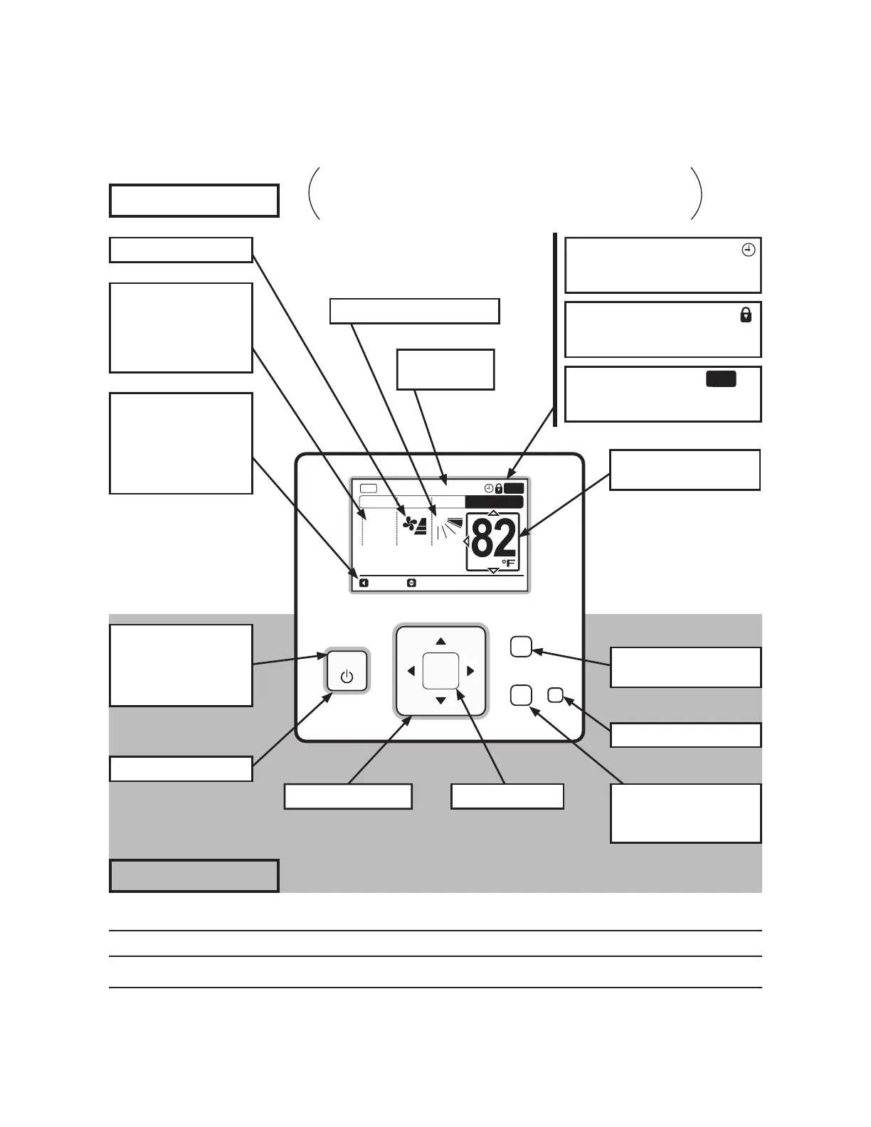
Display Part
OK
Menu
Back/Help
ECO
On/Off
A/C
MODE SPEED
TEMP
COOL
LOUV. Adj.
Meeting Room
LOUV.
FLTR
Filter Sign Indicator
FLTR
is displayed at the set period for
¿OWHUFOHDQLQJ
Operation Lock Indicator
is displayed when the operation
lock function is set. *
Schedule Timer Indicator
is displayed when the schedule
timer function is set. *
Directional Key Enter Key
On/Off Switch
Run Indicator
Illuminates while the
unit is operating, and it
ÀDVKHVGXULQJDEQRUPDO
conditions.
Operation Mode
Indicator
“HEAT” and “AUTO” are
indicated only for the
heat pump type models.
Operation Guide
Indicator
“Central Control” is
indicated while the
controller operation is
prohibited.
Operation Part
ECO Switch
*
Back/Help Switch
To return to the previous
screen.
Menu Switch
*
To display Menu.
Swing Louver Indicator
Fan Speed Indicator
Room Name
Indicator
*
The example below references the control panel and all
adjustable settings. The wired controller display may be
different during actual operation.
Setting Temperature
Indicator
4.2 Wired Controller (CIW01)
NOTE
)RUGHWDLOHGGHVFULSWLRQVUHIHUWRWKH2SHUDWLRQ0DQXDOIRUWKHZLUHGFRQWUROOHU

 Loading...