Chapter - Routine Maintenance
Page Issue 01
OG
6:6
V Range 501 ● 651 ● 801 - Operator’s Guide
Introduction
This chapter highlights some of the basic adjustment and maintenance procedures required
to keep the machine performing efficiently. For more detailed information refer to the
Technical Manual.
ChannelBrushAdjustment
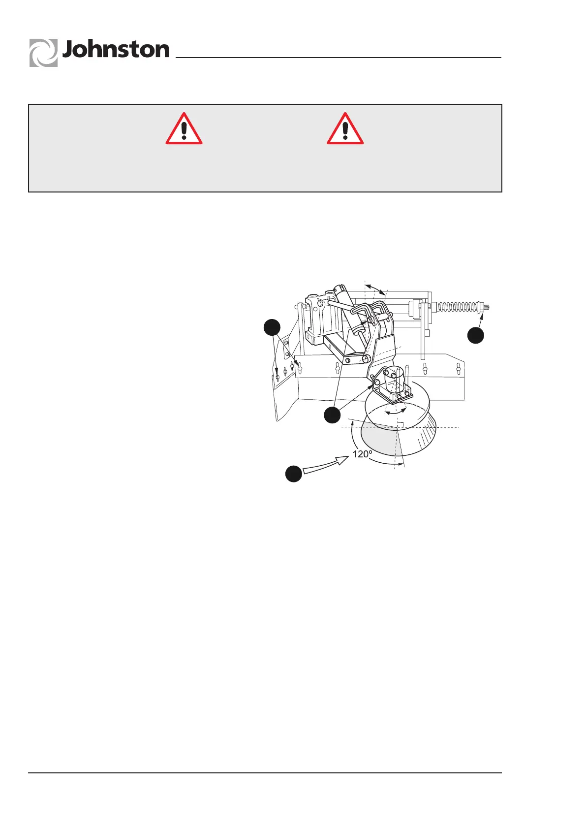
The brush is supported on a pivoting
arm which allows it to float against the
kerb and fold back on impact.
The ‘kick back’ resistance (A) is
adjusted by the compression spring
nut (B) at the rear of the brush
assembly.
Thebrushangleadjustment.
Is set, using adjusters (C), so that
about 120° of circumference towards
front and kerbside is in contact with
the road.
Rubbercurtainadjustment.
These should be set just clear of
the ground using adjusters (D).
Adjustment should be effected with
brush in working position. A cab
control is provided to vary the speed of the brush, also the ground pressure by means of the
Powasave control.
M02OG-101
A
B
C
D
EQUIPMENTADJUSTMENT/MAINTENANCE
Channel Brush Replacement
Removal
It is preferable to have the brush arm in the working position with chassis engine inert and
air supply isolated. Loosen the four flange nuts securing brush stock assembly to the drive
plate. turn slightly to align nuts with holes in plate and remove brush.
Refitting
Reverse of removal procedure. Any loops of steel tines which project above the head of the
stock should be hammered flush before offering up the brush stock assembly to the driving
plate. Loosen flange nuts on brush stock, align brush with holes in drive plate, rotate in the
opposite direction of brush rotation and tighten nuts.
●TheuseofNeedlestickglovesisrecommendedwhenworkingwiththisequipment
●Ensuretheauxiliaryengineisnotrunningandisolatedbeforebrushadjustmentor
replacement is attempted.
Safety Notice
All Copyright and rights are the property of Johnston Sweepers Ltd