Chapter - Routine Maintenance
Page Issue 01
OG
6:16
V Range 501 ● 651 ● 801 - Operator’s Guide
3
2
(i)
M02OG-050
5
(i)
A
G
1
8
6
7
4
9
10
11
D
B
F
C
HH
H
E
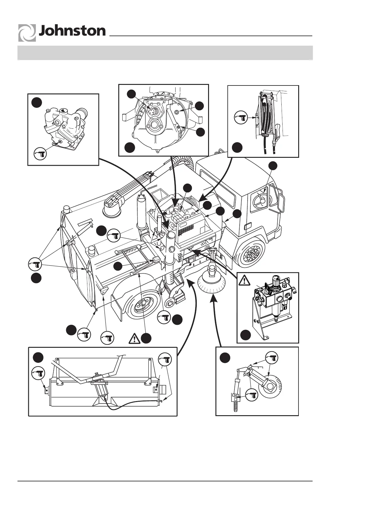
1 Body Prop - Ensure autoprop has
engaged when body is raised.
2 Vitaliser unit - (i) Isolation valve.
3 Water pump.
4 Channel brush.
5 Wide sweep brush - (i) Grease when
renewing brush stock.
LUBRICATION DIAGRAM
Refer to Maintenance Schedules for lubrication intervals
6 ‘Z’ drive gearbox.
7 Supawash hose reel.
8 Wanderhose
9 Rear door
10 Nozzle wheel
11 Body raise cylinder
VT - Twin Engine
All Copyright and rights are the property of Johnston Sweepers Ltd