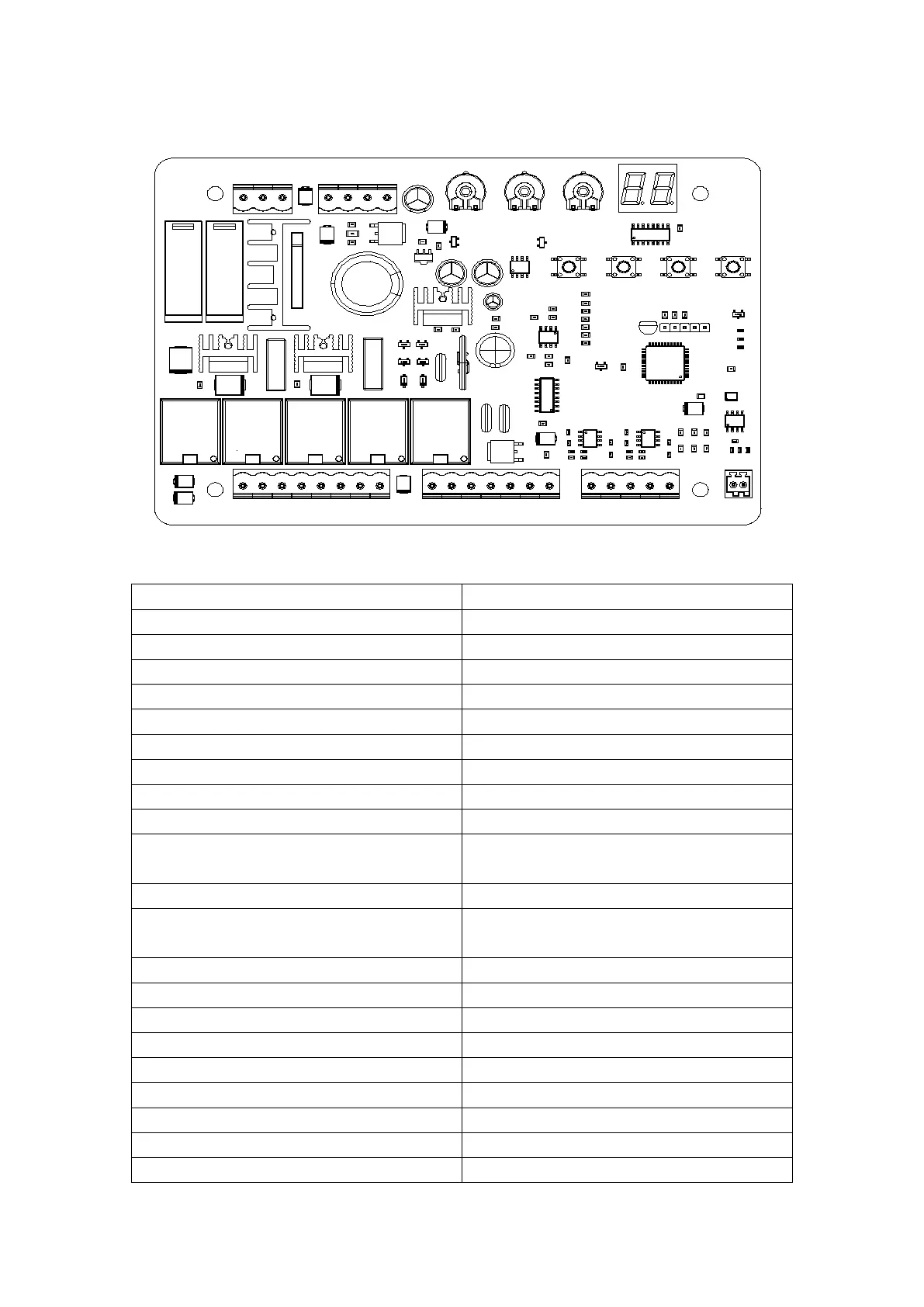
9.2 Control Board Drawing and Instructions
MOTOR1MOTOR1
AC24VINAC24VIN
FORCEFORCE SLOWSLOW
PROGPROG
+
-
SETSET
DOWNDOWN SPEEDSPEED
MOTOR2MOTOR2
-ELOCK+-ELOCK+ -BLK+-BLK+
24V24V
+SOLAR-+SOLAR- +BATT-+BATT-
12V12V COMCOM COMCOM COMCOM OSCOSC GNDGND ANTANTPHPH PEDPEDEM1EM1 LM1LM1 EM2EM2 LM2LM2
Figure 12
Alarm Lamp Output (Note: pay attention to
the negative and positive.)
12V Output Positive (No output under dormant
state)
Motor1 Hall Sensor Power Output
Motor1 Hall Sensor Limit Signal Input
Motor2 Hall Sensor Power Output
Motor2 Hall Sensor Limit Signal Input
Photo Sensor Input Active
Single Gate/Pedestrian Mode Input Active
Single Channel Input Active