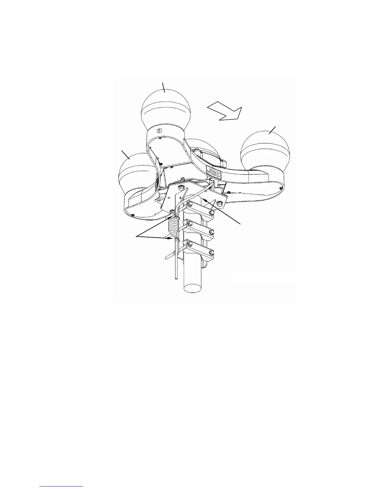
2-9
2. Fix both ends of the clamp filter (large) by using bundling bands (long) to secure the cable.
Let the bands go through the holes of the mounting base.
3. Connect the display unit and check the installation condition.
Check the bow direction on the screen of the display unit. If direction error is found (more
than around 5 degrees), adjust the position of the sensor (the sensor mounting plate has
slotted holes). Also, for reinforcement, weld the mounting base and the pole as necessary.
BOW
GPS3
GPS1
GPS2
Installation figure
Fix by bundling
bands (long).
Contact the pole end to
the mounting base.