2-18
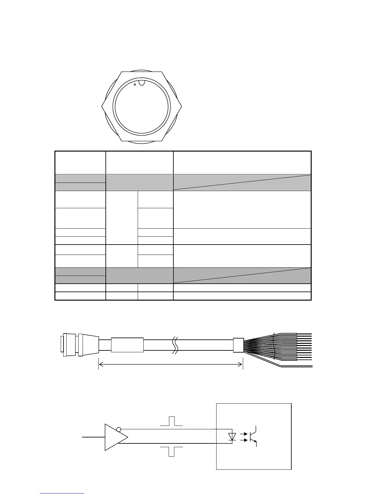
[Data IN/OUT 1 Connector]
DATA IN/OUT 1
Data Cable: CFQ-5374 (option)
Terminal
Number
(CFQ-5374)
Name Explanation
1 (Brown)
2 (Red)
Unused
3 (Orange) SD-A
4 (Yellow) SD-B
Output signal is sent from this terminal by
connecting the sensor.
Outputs as defined by "Sensor Through"
configuration.
(Refer to "5.3.7 Data I/O Settings (DATA I/O)")
5 (Green) SC-A
6 (Blue)
Sensor
Through
SC-B
Outputs clock when AD-10 configuration is
performed for "Sensor Through".
7 (Purple) A
8 (Grey)
TXD3
B
Outputs as defined by "Data OUT 3"
configuration.
(Refer to "5.3.7 Data I/O Settings (DATA I/O)")
9 (White)
10 (Black)
Unused
11 (Pink) GND ISO Connects serial transmission cable ground.
12 (Light Blue) GND Chassis ground
Appearance of Connection Cable
① ⑧
② ⑨ ⑦
⑪ ⑫
③ ⑩ ⑥
④ ⑤
CFQ-5374
3m
A
B
External Device