8.4 Replacement of Major Parts
yyyy
yyyy
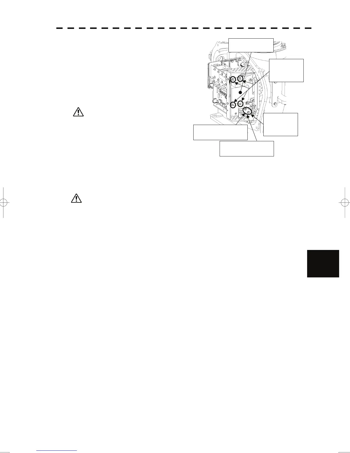
(4) Make sure there is no charge remaining in the
modulation high-voltage circuit board, and then
remove the screws (two M4 screws) holding the
magnetron cables (yellow and green) in place.
Remove the green
cable.
Remove the yellow
cable.
Magnetron
Remove th
four screws.
e
Remove the
two screws.
(5) Remove the screws (four M4 screws) holding the
magnetron in place, then replace the magnetron
after cutting the leads (yellow and green) for the
replacement magnetron to an appropriate length.
Use a shielded screwdriver because the
contact of the metal tool with the magnetron
causes deterioration of its performance.
(6) After having replaced the magnetron, reassemble the unit by following the disassembly procedure in the
reverse order. Do not forget to tighten the bolts and screws, and do not forget to reconnect the cables.
Extreme care should be taken to connect the leads (yellow and green) to the magnetron for
prevention of contact with other parts or the casing. Contact may cause them to discharge.
8
8-18
 Loading...


