EasyManua.ls Logo

JRC JMA-5332-12 - Page 462

JRC JMA-5332-12
492 pages
To Next Page IconTo Next Page
To Previous Page IconTo Previous Page
Loading...
RF AMP
MOTOR
DRIVER
PC1501
AC100-115V, 50/60Hz, 1φ
MOTOR
RELAY
PC1201
ERROR
Junction Box
NQE-3151A
SLOT ANTENNA
MOTOR
B101
SAFETY
SWITCH
S101
MAG
V101
PULSE
TRANS
SWITCHING
CIRCUIT
PC201
MH
GENERATOR
AVR
PC1001
ΦA,ΦB,ΦZ
FILTER
DUMMY
LOAD
Scanner Unit
NKE-1130
POWER
SUPPLY
CIRCUIT
Status
Tx Trigger/Pulse Width
ENCODER
ROTARY
JOINT
INTERFACE CIRCUIT
IF AMP
VIDEO
AMP
Receiver
Bandwidth
Control
Tune Control
DIODE
LIMITER
MULTI RAIN SEA
NMEA I/F
NMEA I/F
NMEA I/F
NMEA I/F
NMEA I/F
Relay
Filter
Power Supply
GAIN
EBL VRM
CPU
PWR
SW
Signal Proc ASIC
STC/FTC/CFAR
IR/AVE/GZ alarm
Radar Draw ASIC
Scan convert
Scan correlation
Trail process
Graphics ASIC
Map draw
Graphics draw
Main CPU
Communication
User I/F
Main control
TrackBall
Buzzer
Key Matrix
Encoder
RS422 I/F
ISW
SEL
ADC
RS485
I/F
RS422 I/F
Sub
CPU
ARPA
DSP
Sweep
memory
Frame memory
Radar Echo
Radar Trails
Frame memory
Map
Graphics
DDR SDRAM
work
FROM
program
SRAM
Back-up
CPU
AIS
SIO
SIO
SIO
SIOSEL
SEL
PWRCNT
MTR+/-
+12V
OPTION
Operation Unit NCE-5171
LCD Monitor NWZ-173
19inch LCD
I/F
Radar Process Unit NDC-1417
GYRO
LOG
GPS
COMPASS
GPS
PC
NAV2
NAV1
Analog RGBPWRCNT
OPTION
OPTION
DC24V
-10%
+50%
GYRO I/F
ISW unit
(OPTION)
Receiver
Relay Control
External
Display
AC100-115/
220-240V,
50/60Hz, 1φ
AC220-240V, 50/60Hz, 1φ
付図 2 JMA-5332-12 レーダー装置回路動作説明図
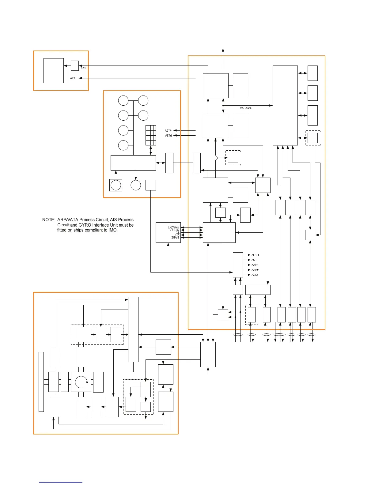
Fig.2 Block Diagram of JMA-5332-12 RADAR

Table of Contents

Other manuals for JRC JMA-5332-12

Related product manuals