4-2
JMA-9100/7100 Installation Manual > 4.INITIAL SETTING > 4.1 GYRO INTERFACE SETTING
4.1 GYRO INTERFACE SETTING
4.1.1 GYRO INPUT SETTING (STEP/SYNC setting)
The gyro interface circuit of this apparatus is designed to be compatible with
almost all types of gyro compasses by flipping of a switch.
Before the power is turned on, switches S1, S2, S5, S6, S7 and jumper JP1 on the
gyro interface circuit (PC4201) shall be set in accordance with the type of the
compass being used according to the procedures described below. Those have
been set at the gyration ratio of 180X and are compatible with the step type before
delivery from factory. Be sure to check the type of the gyro compass used in own
ship and make settings according to the procedures below.
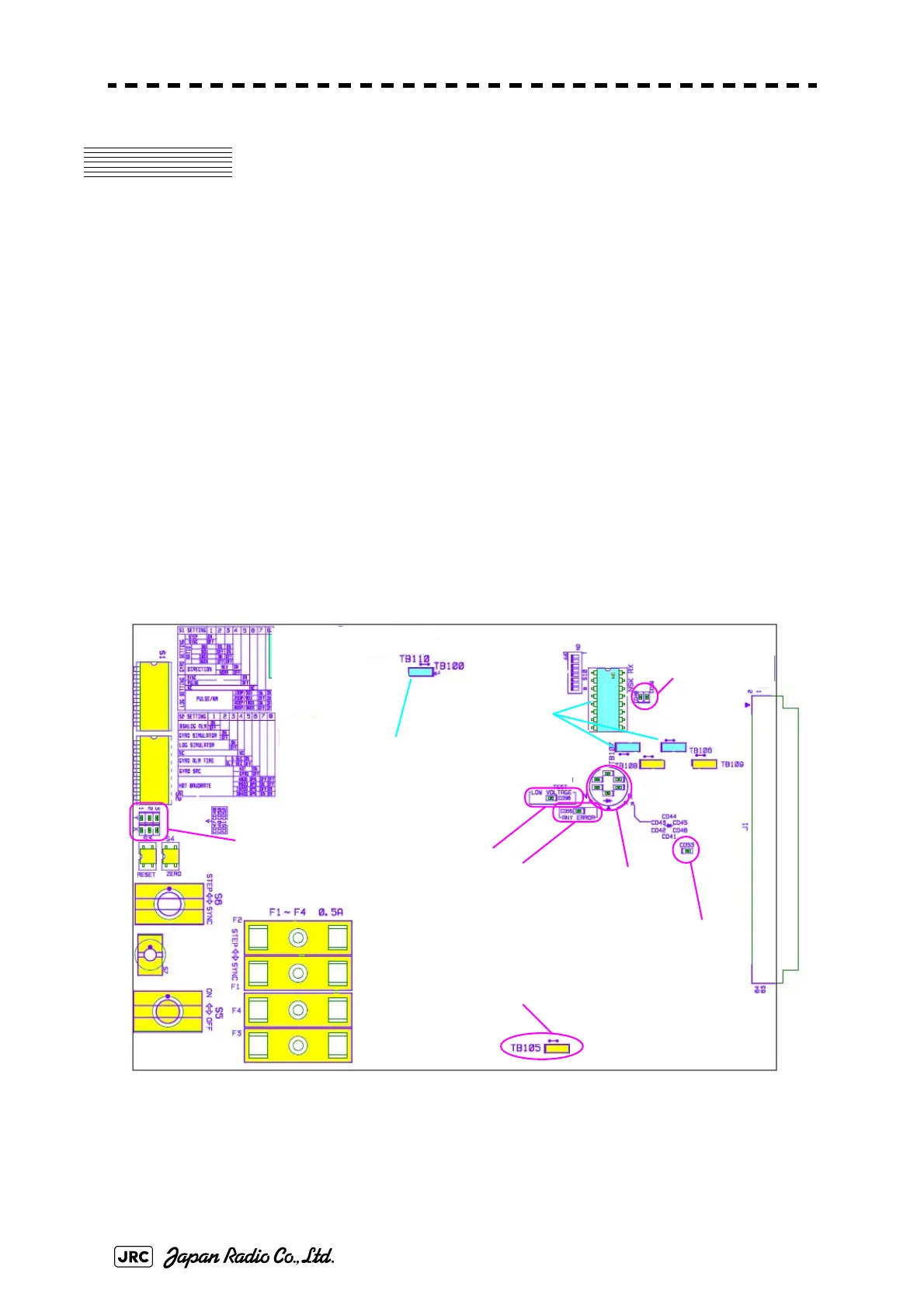
Fig 4-2: Gyro Interface Circuit Setting Location
Step-motor type: DC24V to DC100V
Synchro-motor type: The primary excitation voltage is AC50V to 115V
GYRO INPUT SIGNAL
INDICATOR LED
ジャイロ入力信号LED
GYRO SIGNAL PROCESS
INDICATOR LED
ジャイロ 信号処理表示LED
LOG PULSE
INDICATOR LED
ログパルス表示LED
ERROR INDICATOR LED
エラー 表示LED
GYRO LOW-VOLTAGE
ALERT LED
ジャイロ低電圧警告LED
SERIAL SIGNAL
INDICATOR LED
シリアル信号表示LED
OPEN
プラグ無し
KEEP DEFAULT
設定不要
LOW-VOLTAGE GYRO
SETTING
ジャイロ低電圧時に設定

 Loading...


