JMA-9100/7100 Installation Manual > 2.INSTALLATION OF SCANNER UNIT > 2.1 EQUIPMENT CABLE
2-7
2
2.1.5 Connection to the display-unit side terminal block
The terminal block of the display unit's terminal board circuit is a plug terminal
block which does not require a crimp-type terminal. Connection procedures are
described below.
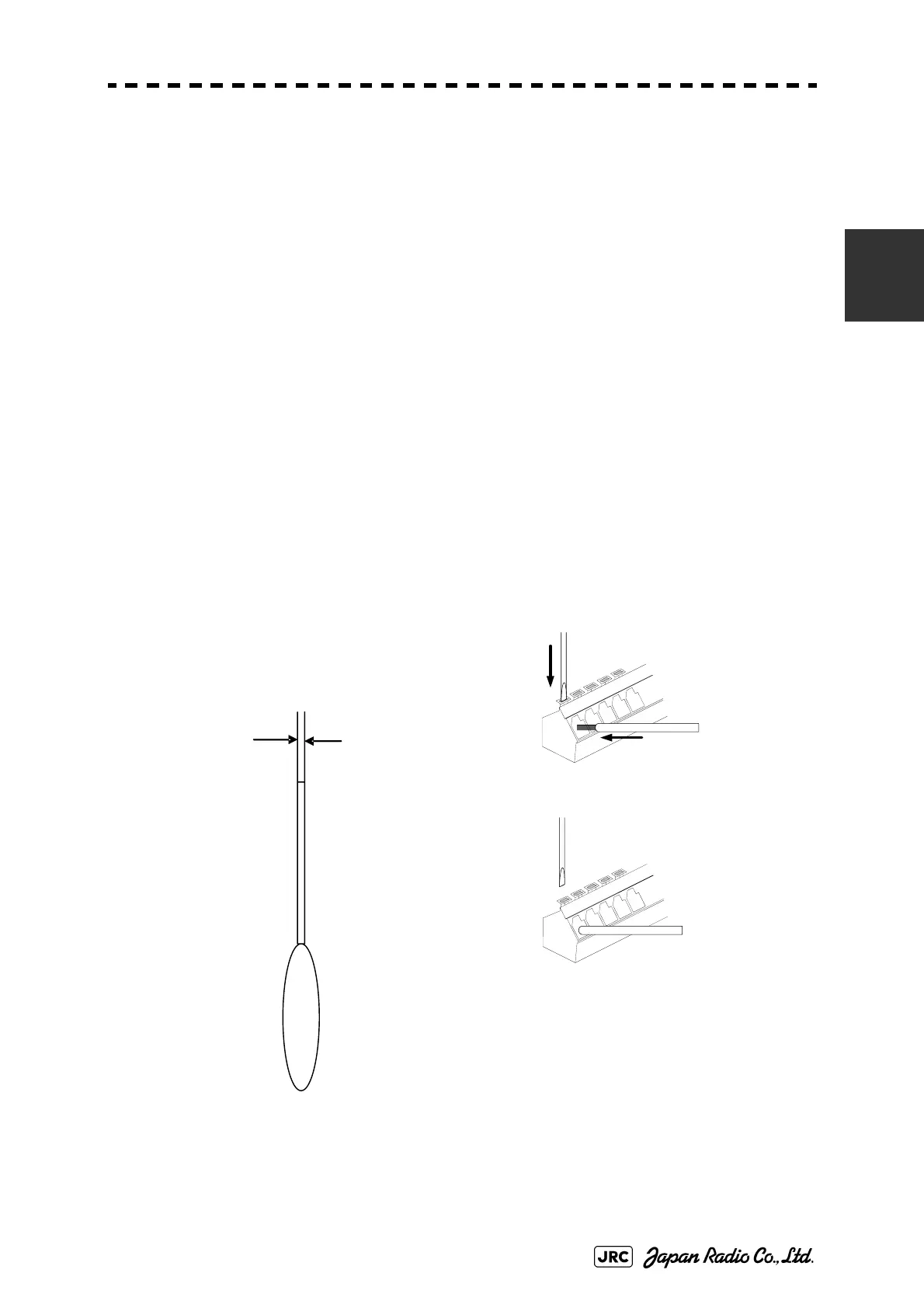
1) Use a tool, such as a flathead screwdriver, to press the control so as to open
the cable inlet.
2) Check the length of the uninsulated portion of the electric wire and its
alignment, and then insert the electric wire until the end comes in contact
with the rear of the inlet.
3) Remove the tool from the control and securely tighten the cable. Properly
connect the cable in reference to the inter-board connection diagram.
4) After the cable has been connected, gently tug at the cable to ensure that it is
securely fastened.
Fig 2-10: Terminal block connection method
2.5mm
Appropriate
flathead
screwdriver
Press down the lever to
open the cable inlet.
Insert the cable until it comes
contact with the rear of the inl
Gently tug at the cable to ensu
that it is securely fastened.

 Loading...


