5-12
JMA-9100/7100 Installation Manual > 5.OPTION UNIT > 5.1 INSTALLATION OF INTERSWITCH UNIT
3)
When a system consists of two devices, make sure that both left and right
radars conform to the screen indication.
4)
When a system consists of three devices, make sure that the CH number
and the display unit position are arranged as intended.
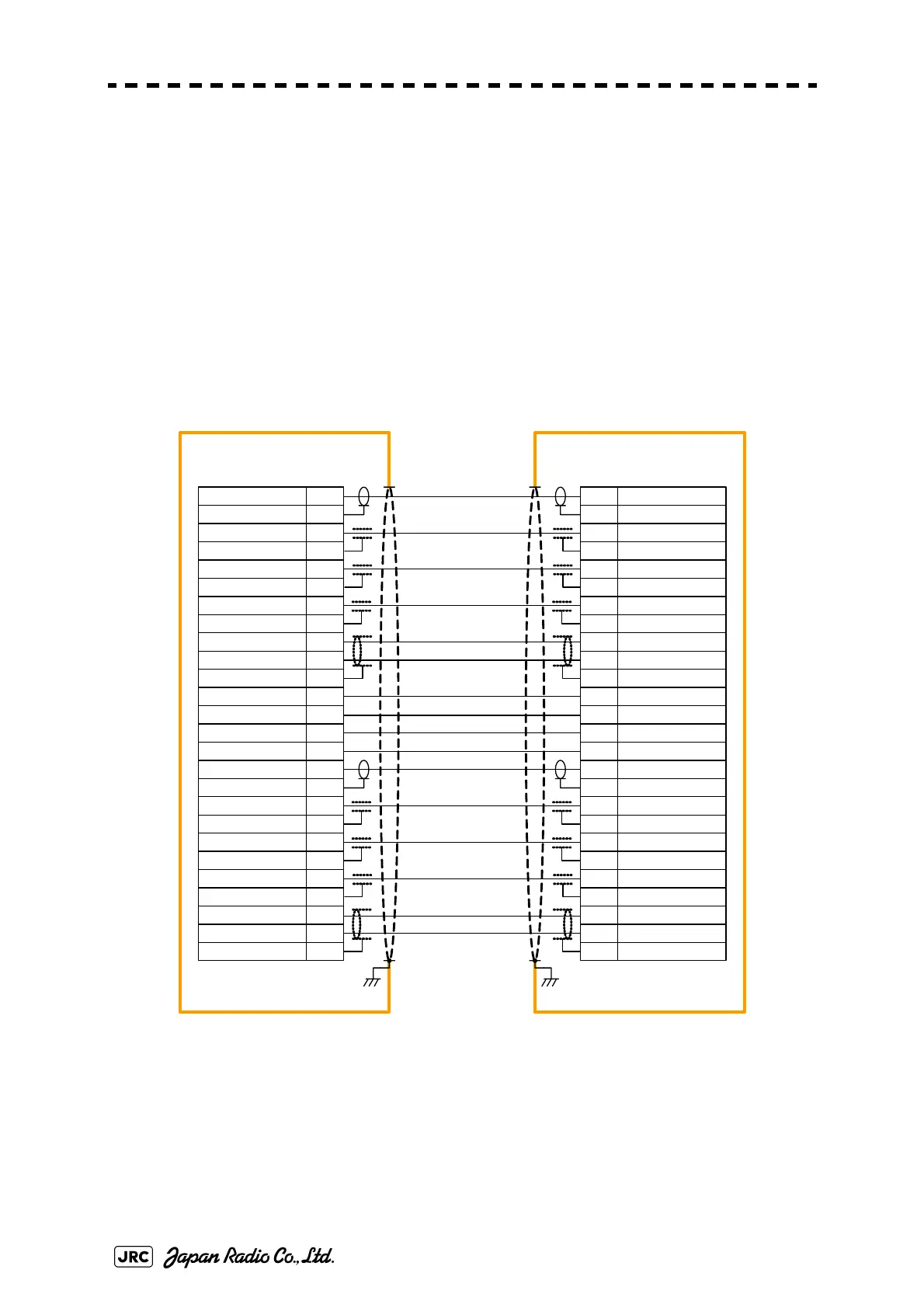
5.1.6 Inter-board connection diagram
1)
NQE-3141-2A
Fig 5-12: NQE-3141-2A Inter-board connection diagram
VDIN 1
VDIN 1E
TRIGIN 1
TRIGIN 1E
BPIN 1
BPIN 1E
BZIN 1
MTRIN 1+
MTRIN 1-
BZIN 1E
MTRIN 1E
PWRIN 1+
PWRIN 1E
PWROUT 1
PWRO UT 1E
VDOUT 1
VDOUT 1E
TRIGOUT 1
TRIGOUT 1E
BPOUT 1
BPOUT 1E
BZOUT 1E
MTROUT 1+
BZOUT 1
MTROUT 1 -
MTORUT 1E
1
2
3
4
5
6
7
8
9
10
11
12
13
14
15
16
17
18
19
20
21
22
23
24
25
26
VDIN 1
VDIN 1E
TRIGIN 1
TRIGIN 1E
BPIN 1
BPIN 1E
BZIN 1
MTRIN 1+
MTRIN 1-
BZIN 1E
MTRIN 1E
PWRIN 1+
PWRIN 1E
PWROUT 1
PWRO UT 1E
VDOUT 1
VDOUT 1E
TRIGOUT 1
TRIGOUT 1E
BPOUT 1
BPOUT 1E
BZOUT 1E
MTROUT 1+
BZOUT 1
MTROUT 1-
MTORUT 1E
1
2
3
4
5
6
7
8
9
10
11
12
13
14
15
16
17
18
19
20
21
22
23
24
25
26
TB4201
ISW IN/OUT
TB4201
ISW IN/OUT
DISPLAY 1
DISPLAY 2
1
2
BLUE
YELLOW
GREEN
WHITE-BLUE
WHITE-WHITE
ORANGE
BLACK
PINK
BROWN
RED
PURPLE
CLEAR
WHITE-YELLOW
WHITE-WHITE
NCD -4990
NCD -4990
H -2695111153
(JRC SUPPLY )
 Loading...


