JMA-9100/7100 Installation Manual > 5.OPTION UNIT > 5.1 INSTALLATION OF INTERSWITCH UNIT
5-7
5
1)
Securely ground the included earth plate to the hull's earth.
2)
Connect the cable (2695111153) between interswitch unit NQE-3141-8A
and terminal board TB4201 located on the each radar display unit. See Fig
5-13: NQE-3141-4A Inter-board connection diagram.
3)
Confirm the installation. See Section 5.1.5Confirmation after installation.
Fig 5-8: NQE-3141-8A Cable Entrance
5.1.4 Setting
Since settings have been normally made upon shipment from factory, it is advised
to only confirm the settings.
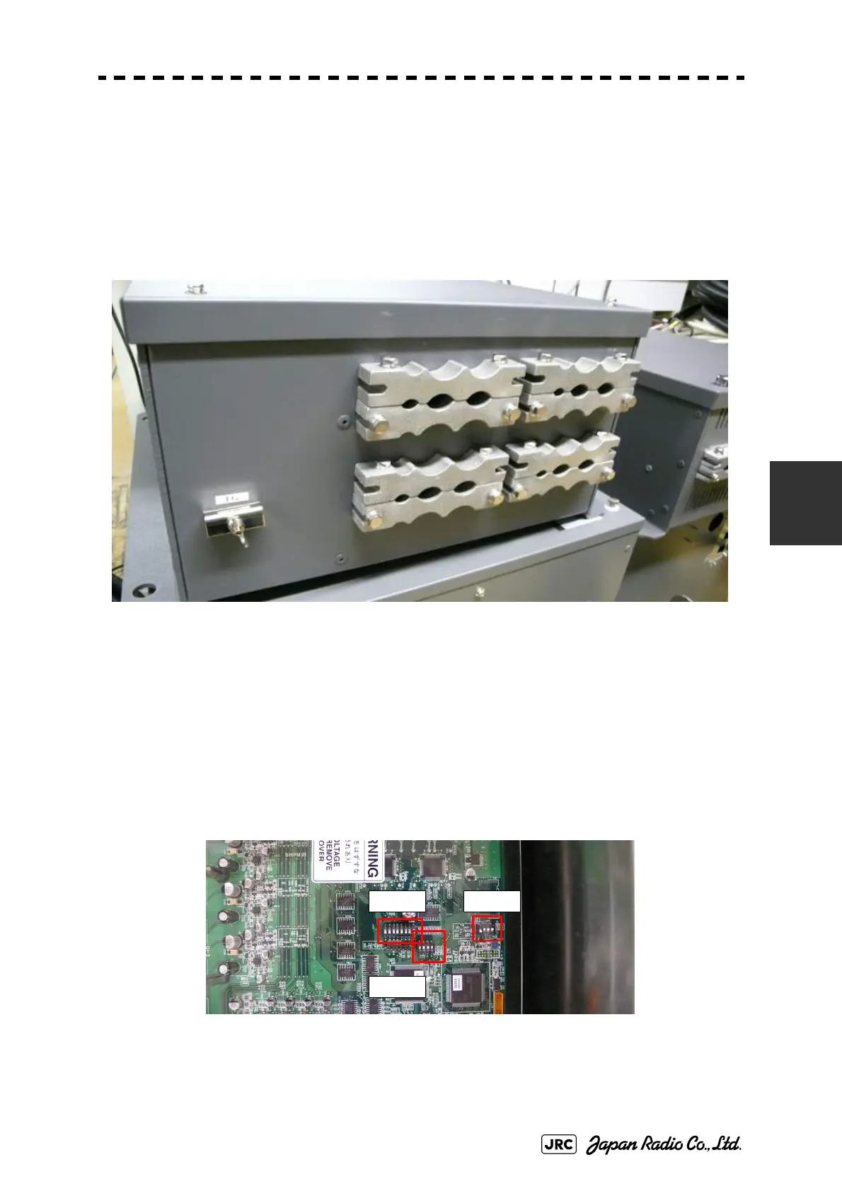
a. Setting of NQE-3141-2A,NQE-3141-4A
Set dip switches SW11, SW12, and SW13 as shown below.
Fig 5-9: CML-304R DIP Switch
SW11
SW13
SW12
 Loading...


