5-62
JMA-9100/7100 Installation Manual > 5.OPTION UNIT > 5.3 INSTALLATION OF VDR
5.3 INSTALLATION OF VDR
5.3.1 Connections
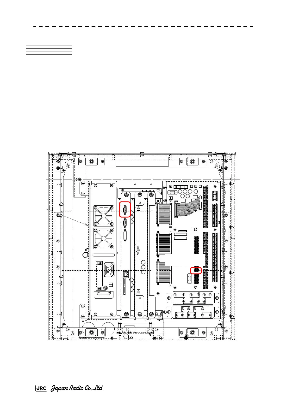
The VDR video signal (analog RGB) output connector is J4409 of radar
processing circuit CDC-1324 located in the display unit (processing unit). See the
drawing below.
When JRC's VDR is used, by connecting it to TB4601(21,22)MNTTX± of
terminal board circuit CQD-2097 located in the display unit (processing unit), it is
possible to use the online maintenance function.
Fig 5-62: VDR connection connector / terminal block
J4409
TB4601(21,22)
MNTTX+,-

 Loading...


