3-16
JMA-9100/7100 Installation Manual > 3.INSTALLATION OF DISPLAY UNIT > 3.2 INSTALLATION OF AC-DC CONVERTER NBA-5135
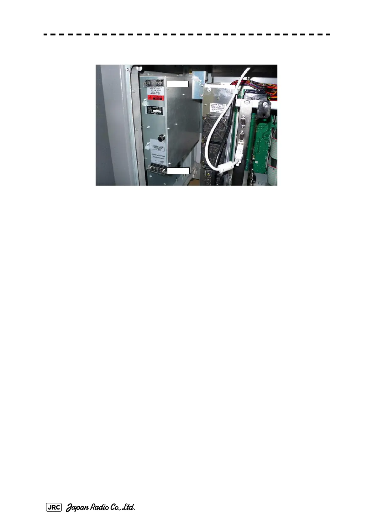
Fig 3-16: Equipment 6 of NBA-5135 (NCD-4990)
Connect terminal block TB521 located at the upper part of NBA-5135 to CBD-
1661.
Use cable H-7ZCRD1342(W406) (No.5, gray, thin, and 60cm in
Table3-1 :
NBA-5135 Packing List
).
Connect U to U, and V to V according to the label of the cable. The FG terminal
should be disconnected.
Terminal block TB522 located at the lower part of NBA-5135 is a DC output
terminal block.
Connect red, green, white, and orange-color equipment cables (CFQ-6912-**) to
the + terminal. Crimp two cables each to the round, crimp-type terminal (V2-M4
recommended) and fasten them tightly.
Connect purple, brown, blue, and gray equipment cables to the - terminal. Crimp
two cables each to the round, crimp-type terminal (V2-M4 recommended) and
fasten them tightly.
The FG terminal should be disconnected. Confirm proper connection by referring
to Section Section 6.3 INTER-BOARD CONNECTION DIAGRAM.
After wiring connection has been done, install the guard (No.1 and 7 in
Table3-
1 : NBA-5135 Packing List
).
TB521
TB522

 Loading...


