3 – 101
3 Checking Receiver System
The maximum range of the PM pattern on display indicates a fall of the sensitivity of the receiver
system.
Procedures of Checking
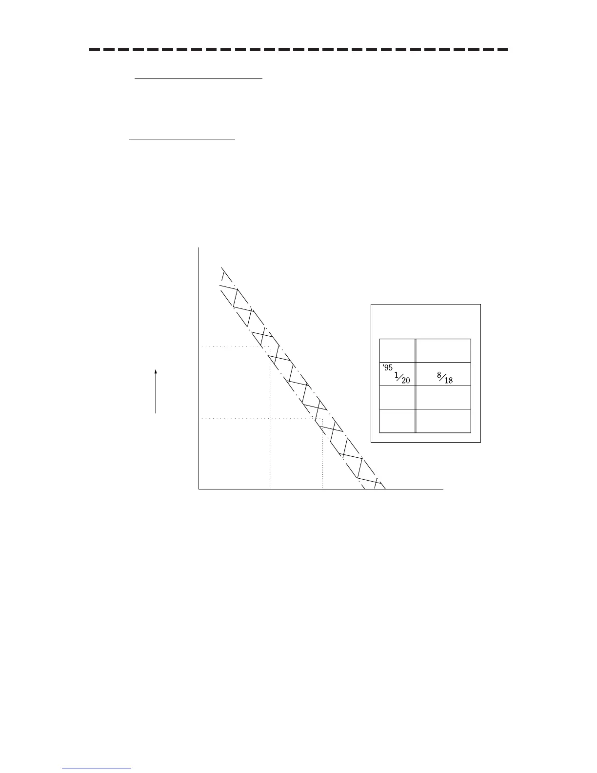
q Measure the maximum range rmax from the PPI center to the PM pattern on display using a
VRM (Variable Range Marker).
w Obtain a fall of sensitivity R (rmax) to the maximum range rmax referring to the Calibration
Curve II.
The value R (rmax) represents a current sensitivity fall in the receiver system.
Fig. 3

 Loading...


