KE2000 Installation Manual
28
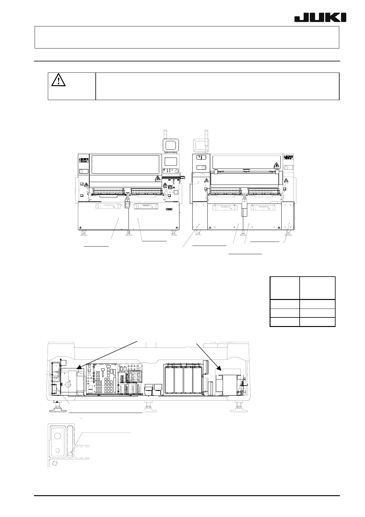
11-2. 2010/2020/2040
11-2-1. Standard Machine
DANGER
DANGERDANGER
DANGER
Prior to connecting the power cord, check to make sure that the power is
not applied to the power supply circuit to be connected (in the form that
the circuit breaker on the power distribution panel is open, etc.).
<
Procedure
>
1.
Detach the cover RBCR30 and cover RBR30.
2.
Connect each line of the power cord to the terminal block shown
in Figure 11-2-1-2 as shown in Table at right. Connect the FG
line to the FG line connection tap on the base frame.
※
※※
※Use the power cord and the FG line with the diameter of 6 mm
2
or more.
3.
After the power cord
has been connected to
the terminal block,
attach the insulation
cover firmly.
※When it is necessary to change
the set voltage at the site, first
remove the covers ① and ②
shown in Figure 11-2-1-2, then
change the voltage by switching
both tabs on the inside two
transformers (main power
transformer and Yc-axis power
transformer).
Fig 11-2-1-2
① ②
Power
supply
Terminal
block No.
U
1
V
2
W
3
Terminal block
(
Standard
Power cord insertion port
Viewed from the rea
of the main unit
Viewed from the rea
of the main unit
Cover RBR
Cover RBL
Cover RBR30
Cover RBCR30
Cover RBCL30
Cover RBL30
Fig 11-2-1-1

 Loading...


