KE2000 Installation Manual
36
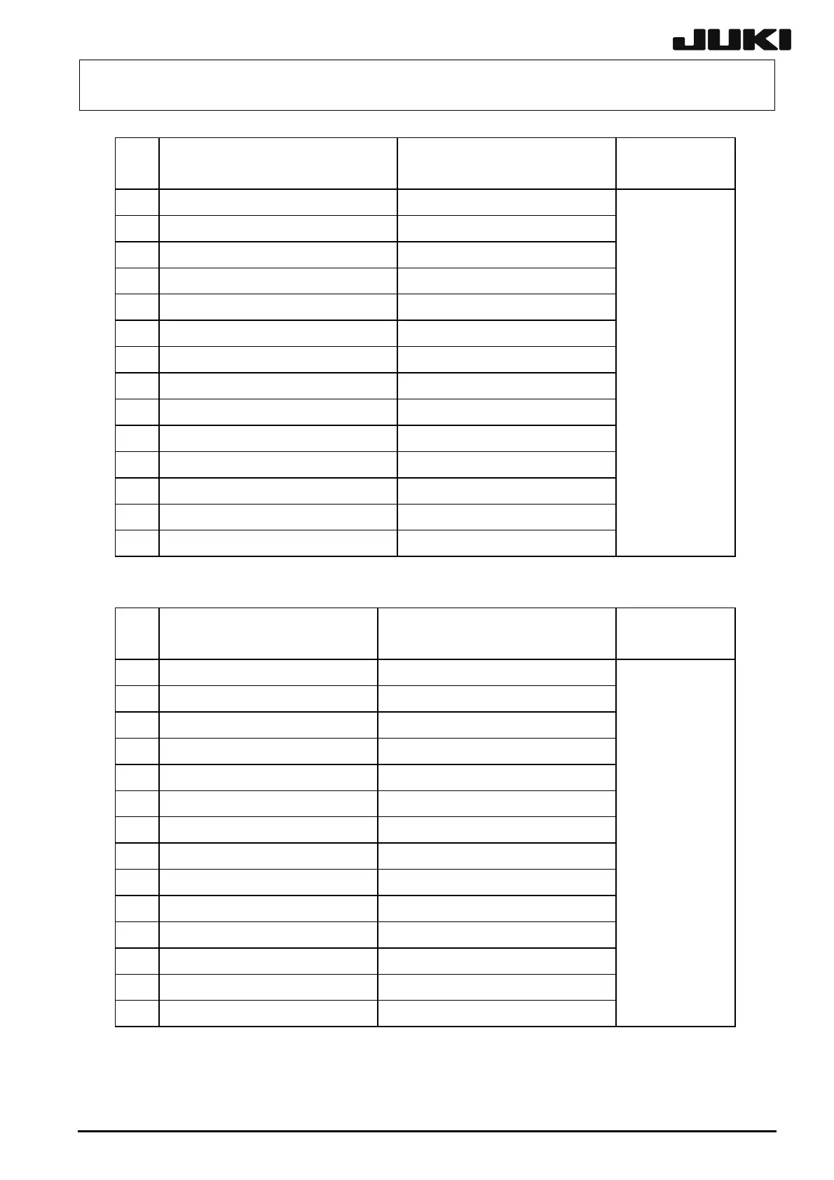
Table 13-1-1 Pin assignments of the connector on the front left side of the main unit
Signal name
(Transport direction :left to right)
Signal name
(Transport direction :right to left)
Connector type
1
READY OUT + READY IN +
2
READY OUT - READY IN - (GND)
3
BOARD AVAILABLE IN + BOARD AVAILABLE OUT +
4
BOARD AVAILABLE IN - (GND) BOARD AVAILABLE OUT -
5
N.C N.C
6
N.C N.C
7
N.C N.C
8
N.C N.C
9
N.C N.C
10
N.C N.C
11
N.C N.C
12
N.C N.C
13
N.C N.C
14
N.C N.C
AMP
206043-1
Cable connector:
206044-1
Table 13-1-2 Pin assignments of the connector on the front right side of the main unit
Signal name
(Transport direction :left to right)
Signal name
(Transport direction :right to left)
Connector type
1
READY IN + READY OUT +
2
READY IN - (GND) READY OUT -
3
BOARD AVAILABLE OUT + BOARD AVAILABLE IN +
4
BOARD AVAILABLE OUT - BOARD AVAILABLE IN - (GND)
5
N.C N.C
6
N.C N.C
7
N.C N.C
8
N.C N.C
9
N.C N.C
10
N.C N.C
11
N.C N.C
12
N.C N.C
13
N.C N.C
14
N.C N.C
AMP
206043-1
Cable connector:
206044-1

 Loading...


