Rev. 2.0
Maintenance Guide
5-25
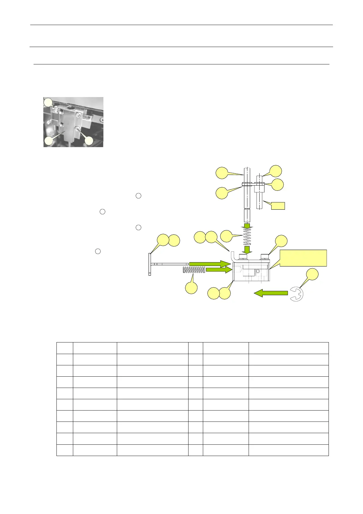
5-13. Replacing the Centering Pin (Option)
1) Loosen the screws d and e of the guide block A to detach the centering pin together with the
guide block.
2
1 3
Figure 5-13-1
2) At this time, also detach the
T-PIN sensor (together with
its bracket) from the
reference side.
Removing the E ring
12
allows you to pull the
centering pin
17
from the
damper block.
Removing the E rings
16
(two in total, top and bottom)
allows you to remove the
centering pin
17
.
When installing a new
centering pin, reassemble the
components in the reverse
order. The E-rings must also
be replaced with new ones.
After the components have
been reassembled, adjust the sensor
position in the same manner as described
in 5-10, Replacing the T-PIN Sensor.
⑦
④
⑰
⑬
⑭
⑯
A
⑤
⑨
⑮
⑧
⑪
B部
右
側=⑧+⑩+⑪
左側=⑦+⑥+⑪
Section B
Right side = ⑧+⑩+⑪
Left side = ⑦+⑥+⑪
⑫
⑥ ⑩
Figure 5-13-2
Part No. Part name
Part No. Part name
1 40000886 GUIDE_BLOCK_ASM 10
L179E721000 DAMPER_BLOCK_R
2 40000887 GUIDE_BLOCK_A_ASM 11
SL6030892TN SCREW
3 40000889 GUIDE_BLOCK_B_ASM 12
RE0300000K0 E-RING
4 40000891 STOPER_SLIDE_LEVER_L 13
40000896 DAMPER_LOCK_PIN
5 40000897 STOPER_SLIDE_LEVER_R
14
40000978 DAMPER_LOCK_LINK
6 L179E621000 DAMPER_BLOCK_L 15
40000950 DAMPER_SPRING
7 40015791 DAMPER_PLATE_L 16
RE0300000K0 E-RING
8
40015792
DAMPER_PLATE_R 17
⎯
CENTERING_PIN
9 40015793 LOCK_SPRING 18

 Loading...


