Rev. 2.0
Maintenance Guide
1-17
1-3. Replacing the Limit Sensor and Origin Near Sensor
1) When replacing only the sensor, it is not necessary to adjust the position.
2) When replacing the sensor together with the bracket, it is necessary to adjust the position.
∗ The home position of the X-axis is the Z-phase of the magnescale. Therefore, there is no
home position sensor for the X-axis.
1-3-1. Replacing the X-Axis Limit Sensor and the X-Axis Home Proximity Sensor
1) Loosen the screw fixing the X-limit sensor bracket and make the adjustment so that the
distances from the X-frame L and R are those shown in the figure below. After the
adjustment has been completed, tighten the screw firmly. (See Figure 1-3-1-1 (M and L
board specifications) and Figure 1-3-1-2 (XL board specifications).)
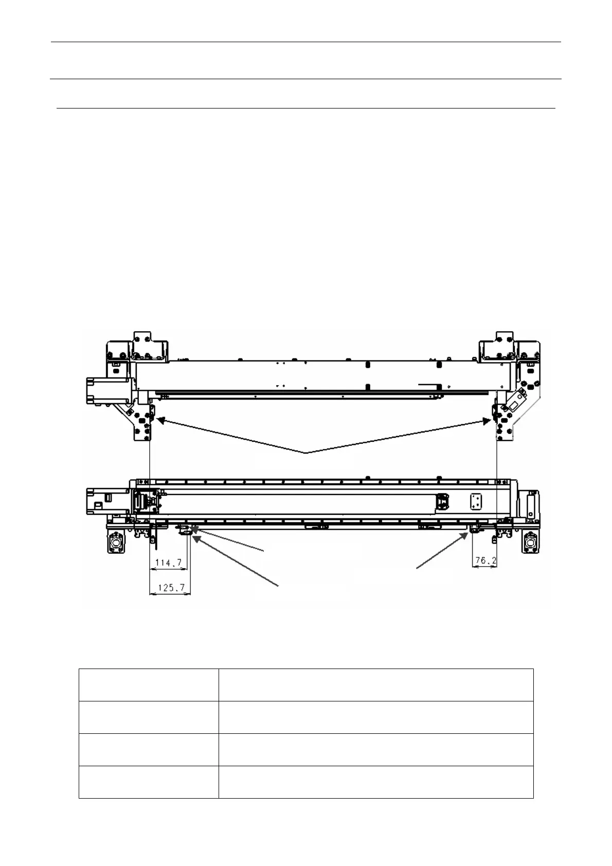
<M and L board specifications (Examples of KE-3020V and VR)>
Stopper rubber affixing surface
X negative limit sensor
X-home position sensor
X positive limit sensor
Figure 1-3-1-1 M and L Board Specifications (Examples of KE-3020V and VR)
Left (X negative limit sensor) Distance between the stopper rubber affixing surface of the X-frame end L
and the center of the sensor: 114.7 mm (KE-3010: 85.7 mm)
Center (X-home position sensor) Distance between the stopper rubber affixing surface of the X-frame end L
and the center of the sensor: 125.7 mm (KE-3010: 96.7 mm)
Right (X positive limit sensor) Distance between the stopper rubber affixing surface of the X-frame end R
and the center of the sensor: 76.2 mm (KE-3010: 112.2 mm)
Clearance between the limit
sensor and the dog
0.8 to 1.5 mm (target: 1.0 mm)

 Loading...


