F 11
0708.GB
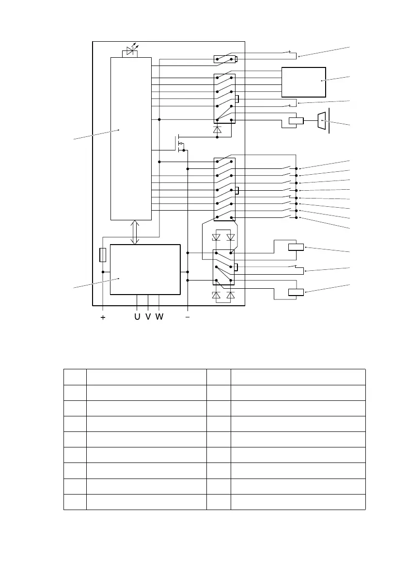
10.3 Circuit diagram
Legend for the circuit diagram
8 Power stage 17 Backward
9 Control 18 Belly switch
10 Move protection 19 Manoeuvering
11 Sensor bearing 20 Lifting
12 Control shaft switch 21 Lowering
13 Retaining brake 22 Lowering valve
14 Setpoint 1 23 Lift limit switch
15 Setpoint 2 24 Hydraulic motor contactor
16 Forward
1
4
1
5
1
36
4
1
10
6
8
5
2
B
0V
A
+15V
X1
X3
X4
X5
8
9
10
11
12
13
14
15
16
17
18
19
20
21
22
23
24
F 11
0708.GB
10.3 Circuit diagram
Legend for the circuit diagram
8 Power stage 17 Backward
9 Control 18 Belly switch
10 Move protection 19 Manoeuvering
11 Sensor bearing 20 Lifting
12 Control shaft switch 21 Lowering
13 Retaining brake 22 Lowering valve
14 Setpoint 1 23 Lift limit switch
15 Setpoint 2 24 Hydraulic motor contactor
16 Forward
1
4
1
5
1
36
4
1
10
6
8
5
2
B
0V
A
+15V
X1
X3
X4
X5
8
9
10
11
12
13
14
15
16
17
18
19
20
21
22
23
24
 Loading...