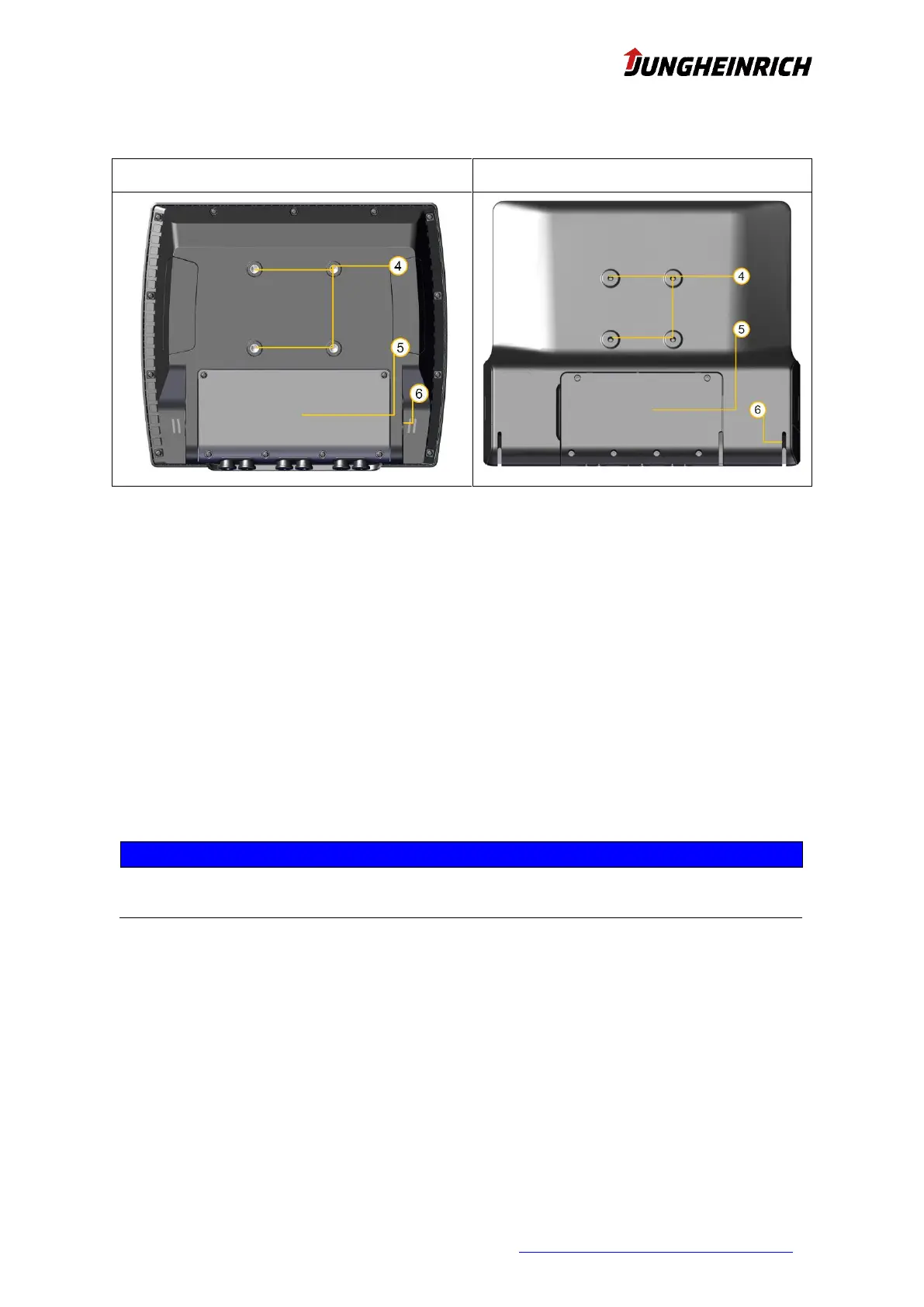
4.1 VESA75 Interface
VESA75 hole pattern according to illustration, position 4.
- Horizontal and vertical distance between the screw holes: 75 mm
- Thread: M6, torque: 8 Nm (recommended)
- Screw-in depth in the threaded bushings: max. 6 mm
4.2 U-Mount Interface
Mount the retaining bracket (see illustration, position 6) on the device using the screws supplied in the
following order from the inside to the outside:
Nord-Lock washer -> bracket -> Nord-Lock washer -> Allen screw (SW 6 mm) -> cover cap.
4.3 Opening the service slot
The relevant safety measures must be observed at all times when handling electrostatically haz-
ardous components. (DIN EN61340-5-1 / DIN EN 61340-5-2).
Remove the 6 screws of the service slot cover (see illustration, position 5) with a Torx Tx10 screw-
driver.
Remove the service slot cover from the device.
 Loading...